
Electronic fly disinfestation

The electronic fly killer circuit is designed for effective pest control by generating a high-voltage electric field that kills flies upon contact. The core of the system is the astable multivibrator configuration created by the ICL 555 timer IC, which oscillates at a frequency suitable for generating the desired square wave output. The values of resistors R1 and R2, along with capacitor C1, are crucial for setting the frequency and duty cycle of the output waveform.
The transistors VT1 and VT2 function as switches that allow the low-voltage square wave signal to control a higher voltage, which is necessary for the operation of the step-up transformer. This transformer is designed to increase the voltage to a level sufficient to create a lethal electric shock when flies come into contact with the grid formed by the spaced wires.
The high-voltage transformer is configured to produce a secondary output that can reach several kilovolts. This high voltage is essential for ensuring that the device is effective in killing flies and deterring them from the area. The wire mesh, made from No. 14 gauge wire, is arranged with a spacing of approximately 6 mm to prevent larger insects from escaping while still being effective against flies.
Safety is a critical consideration in the design of this device. To prevent accidental contact with the high-voltage components, the fly killer should be mounted securely at a height of several meters above the ground. This ensures that children and pets cannot inadvertently come into contact with the electrified grid. Additionally, the device should be fixed firmly to prevent it from being knocked over, which could expose the high-voltage components and pose a safety risk. Overall, this electronic fly killer circuit represents an efficient and effective method for controlling fly populations in a variety of settings.Electronic Fly utilizes high voltage applied to the power line voltage pulse OCS killed flies. Use the following web site when the bait to attract flies, fly Fly online for all to be able to kill the flies. Fly electronic circuit as shown, when the base integrated circuit ICl 555 and the resistor Rl, R2 and the capacitor Cl form astable oscillator circuit, from the foot of ICl output frequency of about 30Hz, 10% duty cycle of continuous square wave. The square wave is coupled via a resistor R3 to the transistor VTl, VT2, promote step-up transformer T boosted amplification, so connected to the high-voltage transformer with a secondary IED kV grid in order to achieve the function of killing flies.
Fly net usable No. l4 wire production, the adjacent wire distance of about 6mm. In order to prevent a child inadvertently high-voltage grid, fly disinfestation should be placed in the ground a few meters high, and should be fixed firmly.
Related Circuits
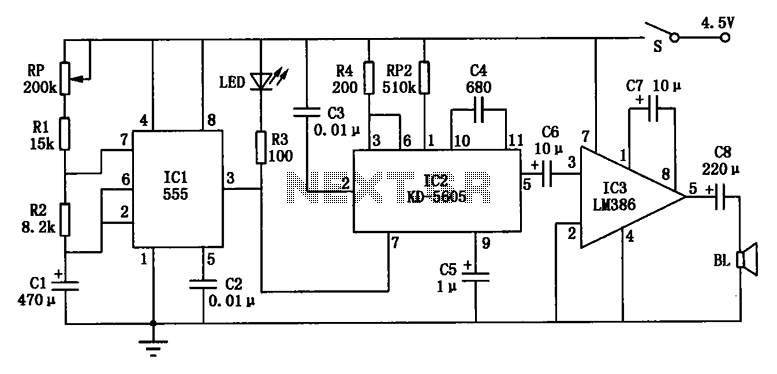
The electronic circuit depicted in Figure cat features the NE555 time base integrated circuit (IC1), along with a potentiometer (RP), resistors (R1 and R2), and a capacitor (C1) that collectively form a time control circuit for regulating intervals. The...
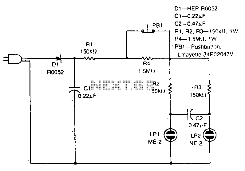
The circuit illustrated simulates the action of flipping a coin by simply pressing switch PB1. More: A straightforward circuit. The circuit operates using a simple mechanism that allows for a binary outcome, akin to a coin flip. When switch PB1...
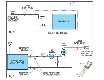
A radio-controlled electronic flash is an essential tool in any photographer's kit. Professionals frequently utilize them, such as wedding photographers. A radio-controlled electronic flash system typically consists of a transmitter and one or more receivers. The transmitter, often mounted on the...
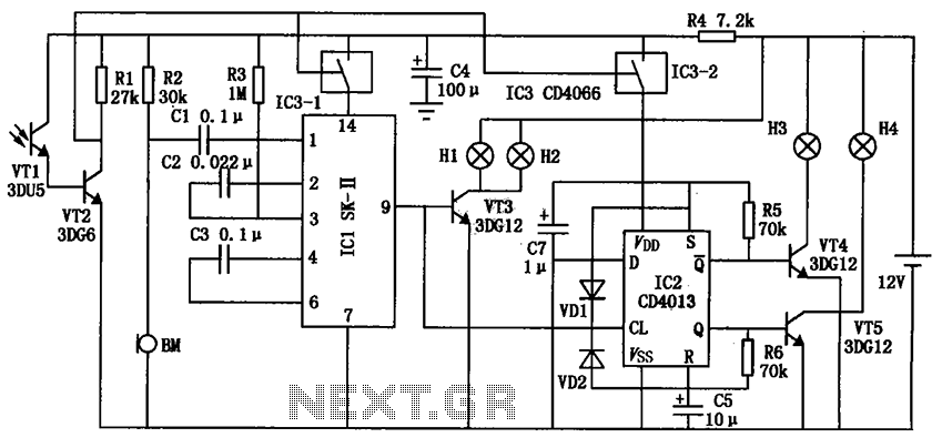
The automatic electronic circuit depicted in the figure consists primarily of a voice circuit, an oscillation circuit, and a driving section for the display circuit. The automatic electronic circuit integrates several essential components to achieve its functionality. The voice circuit...
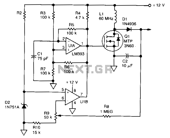
U1 is a dual voltage comparator with open collector outputs. The A side functions as an oscillator operating at 100 kHz, while the B side is part of the regulation circuit that compares a fraction of the output voltage...
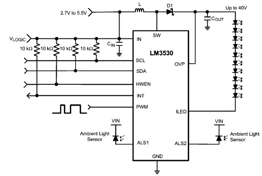
A simple white LED driver circuit can be designed using the LM3530 high-efficiency white LED driver IC, which features programmable ambient light sensing capability and an I2C compatible interface. The LM3530 LED driver can control up to 11 series...