
Electronic coin tosser

The circuit operates using a simple mechanism that allows for a binary outcome, akin to a coin flip. When switch PB1 is pressed, it triggers a change in the output state of the circuit. This can be achieved using a flip-flop configuration, which is a common way to create a bistable multivibrator.
In a typical implementation, the circuit may utilize a 555 timer IC configured in a monostable mode or a D flip-flop. The pressing of PB1 would send a pulse to the clock input of the flip-flop, changing its state from low to high or vice versa.
The output can be represented through LEDs, where one LED lights up for heads and another for tails, providing a visual representation of the coin flip. Resistors may be included in series with the LEDs to limit current and prevent damage.
Power supply connections should be made to the circuit, typically utilizing a 5V or 9V source, depending on the components used. It is essential to ensure proper grounding to maintain circuit stability.
This simple circuit effectively demonstrates fundamental electronic principles while providing an engaging interaction through the physical act of pressing the switch.The circuit shown simulates the flipping of a coin by merely pushing switch PB1 An easy circuit.
Related Circuits
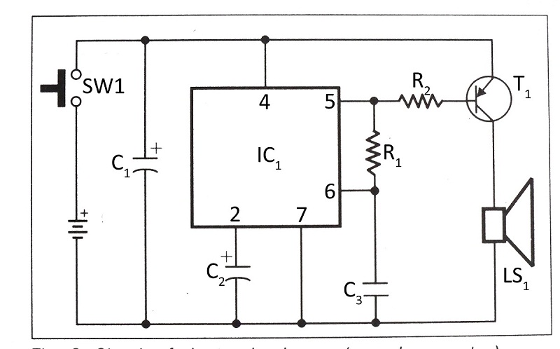
This document presents a verified circuit diagram for a simple, interesting, and cost-effective electronic clapper (sound generator) circuit, along with a description of its functionality. The electronic clapper circuit is designed to activate sound generation through the detection of sound...
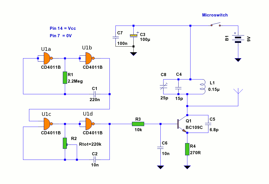
This circuit utilizes a conventional spring-loaded mouse trap, typically available at hardware stores. When a mouse is caught, the circuit activates and transmits an interrupted tone on the commercial FM band to a nearby radio receiver. It is a...
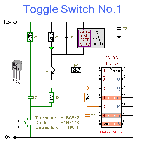
This simple circuit will energize and de-energize a relay with the push of a button. Pressing the button once will energize the relay, while pressing it a second time will de-energize the relay. The accompanying circuit provides a solid...
Wave-filter principles are utilized in various circuits beyond filters, such as in the design of modulation transformers for high-level amplitude-modulated radio transmitters. Some of these transformers are quite large. In plate-modulated power amplifiers, the modulator power necessary for achieving...
This circuit is designed for the selection of alternative sources. It integrates mechanical selection through a rotating switch S1, electronic control of relays RL1 to RL10, and optical indication of the selection via the display DSP1. The circuit operates by...
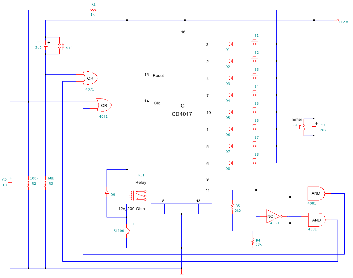
This is a simple yet efficient electronic lock designed to protect electronic systems from unauthorized access. To gain entry, the user must input an 8-digit passcode followed by the "Enter" button. If the correct passcode is entered, the relay...