
Flooding rats Electronic cat
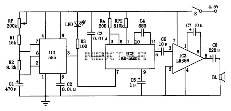
This circuit operates as a timer that generates periodic cat sounds to deter pests. The NE555 timer is configured in astable mode, allowing it to continuously switch between high and low output states. The timing interval, which dictates how long the LED remains on and how often the cat call is emitted, can be adjusted by changing the values of the resistors R1, R2, and the capacitor C1. The potentiometer RP allows for fine-tuning of the charging time, thus influencing the overall frequency of the output sound.
The KD-5605 integrated circuit is a sound generator that produces the desired cat call sound. Its output is connected to a power amplifier (IC3), which boosts the signal to drive a speaker (BL). This amplification is crucial for ensuring that the sound is loud enough to be effective in scaring away rodents.
The feedback loop created by the charging and discharging of capacitor C1 is essential for the continuous operation of the circuit. The internal discharge of the NE555 timer ensures that the capacitor discharges fully, allowing for a consistent timing cycle. This self-sustaining mechanism is what makes the circuit efficient for long-term operation without the need for constant manual intervention.
In summary, this electronic circuit effectively combines a timer, sound generation, and amplification to create a pest deterrent system that is both practical and adjustable based on the user's requirements. The design is straightforward, making it suitable for various applications where pest control is necessary.Electronic circuit shown in Figure cat. ICl time base integrated circuit NE555, it potentiometer RP, resistor Rl, R2 and capacitor Cl form time control circuit for controlling mew interval. IC2 is mew IC KD-5605, it will cure the cat calls within the circuit. Closing the switch S, the power by RP, Rl, R2 to charge Cl, Cl charge to the voltage across the power supply voltage 2/3, pin output low ICl, a light emitting diode LED powered light, while IC2 electrical work, after the output signal is a cat called IC3 power amplifier push speaker BL loud realistic mew, to drive rats purposes. At the same time, ICl internal discharge conduction, Cl stored charge through R2 to IC1 foot discharge.
When the supply voltage drops the voltage across Cl l/3 ±, ICl the pin output high, LED is off, IC2 also lost power to stop working, stop mew. Power and to charge C1 through RP, Rl, R2, circuit so the cycle work.
Related Circuits
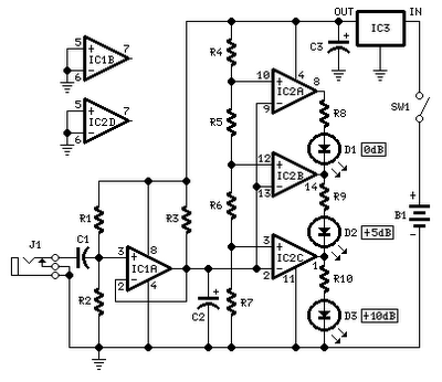
No setup is required: if correct values are used for resistors R3 to R7, LED D1 will illuminate at 0 dB input (0.775V RMS), LED D2 at +5 dB input (1.378V RMS), and LED D3 at +10 dB (2.451V...
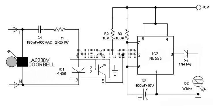
This 6V battery-operated doorbell light circuit can be connected in parallel with any existing AC 230V doorbell. When the doorbell switch is pressed, the bell sounds as usual, and the AC mains supply available across the doorbell is routed...
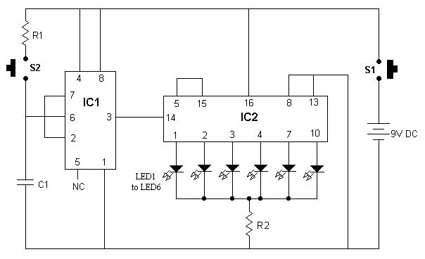
It is advisable to enclose this circuit in a box and label each LED with numbers from 1 to 6. When switch S1 is momentarily pressed, one of the six LEDs will illuminate, with the number corresponding to the...
The circuit is designed for conducting safe experiments with high-voltage pulses and operates similarly to an electrified fence generator. This circuit is engineered to generate high-voltage pulses suitable for educational purposes and experimentation. The design is inspired by electrified fence...

An electronic circuit consists of individual electronic components such as resistors, transistors, capacitors, inductors, and diodes, which are interconnected by conductive wires or traces that allow electric current to flow. The sine wave or sinusoid is a mathematical function...
This electronic organ circuit is straightforward to construct and primarily consists of an emitter-coupled oscillator formed by transistors T2 and T3. A square wave voltage can be obtained from the collector of T3 (X2), which imparts a clarinet-like quality...