
Electronic Canary

The electronic chirping canary functions as an auditory signaling device, capable of generating a variety of chirping sounds that mimic those of a real canary. This device can serve multiple purposes, including functioning as an alarm system, providing sound effects for entertainment, or acting as a novel replacement for a traditional doorbell.
The circuit typically consists of a microcontroller or sound generator IC that is programmed to produce specific chirping patterns. When the device is activated, it can utilize a small speaker or piezo buzzer to emit the chirping sounds. The circuit may also include a power supply, such as batteries or a DC power adapter, to ensure consistent operation.
For alarm functionality, the circuit can be equipped with a motion sensor or a push-button switch. In the case of the motion sensor, the device will activate the chirping sound upon detecting movement within its vicinity, alerting users to potential intrusions. Alternatively, the push-button switch allows users to manually trigger the chirping sound, making it suitable as a doorbell replacement.
In terms of design, the circuit layout should prioritize low power consumption to extend battery life, especially if portable. Additionally, the use of a microcontroller allows for programmability, enabling the user to customize the frequency and duration of the chirps. The device may also incorporate visual indicators, such as LEDs, to complement the auditory signals.
Overall, this electronic chirping canary represents a versatile and engaging solution for sound generation, with practical applications in security and home automation.An electronic version of a chirping canary. May be used as an alarm, a sound effects generator or perhaps a replacement doorbell.. 🔗 External reference
Related Circuits
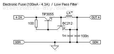
This is adjustable electronic fuse that can be used to protect power supplies from short circuits or can be also used to limit the current usage. It can be adjusted for currents from 100mA up to 4.3A. An adjustable electronic...
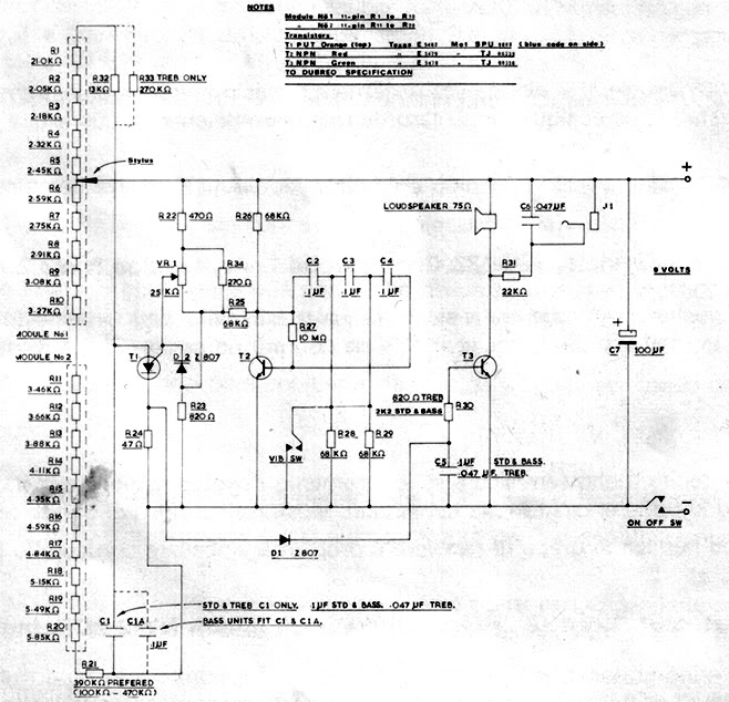
A recently discovered schematic appears to be authentic and does not include the 555 timer. Additionally, a picture of Brian Davis on this page shows him holding the etch mask, which does not exhibit any features resembling a socket...
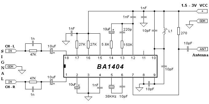
The BA1404 can be utilized to create a simple and effective FM stereo modulator electronic project. This BA1404 FM stereo modulator device operates within the FM broadcast band (75-108 MHz) and requires only a few common external components. The...
Related components PDF download: ICL7106CD4036. The LCD electronic thermometer circuit is illustrated. The temperature sensor KTY10 exhibits a strong linear relationship between temperature and resistance. Points A and B (Measurement display circuit) can be connected with a 100-meter wire....
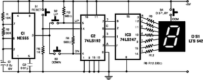
The following circuit illustrates the NE555 Timer used in an electronic scoring game circuit diagram. Features: The circuit consists of a timer integrated circuit (IC), along with various additional components. The NE555 timer is a versatile and widely used integrated...
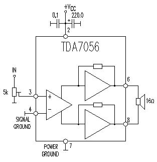
This TDA7056 power audio amplifier circuit diagram project is designed to deliver a maximum output power of 1 watt into an 8-ohm load when powered by a 6-volt supply, or a maximum output power of 3 watts into a...