simple electronic organ

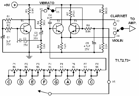
This electronic organ is simple to construct and can provide hours of enjoyment, particularly for children. The circuit is fundamentally an emitter-coupled oscillator consisting of transistors T2 and T3. A square wave voltage can be sampled from the collector of T3 (X2). This signal gives the tone a clarinet character. Without the square wave signal, the sound produced by the emitters of T2 and T3 (X4) has a violin character. An additional vibrato signal can be added to this basic sound through switch S1. The frequency of the vibrato is approximately 6 Hz, and its amplitude is determined by resistor R4, which can vary from 100 kΩ to 300 kΩ. Experimenting with different values is encouraged. The keys can be made of either metal plates or etched printed circuit. The trimmers P1 to P8 adjust the pitch of each tone. The tones can be drastically changed by altering the value of capacitor C4.
The electronic organ described operates using a straightforward emitter-coupled oscillator configuration, which is a common design in audio synthesis applications. The primary components, transistors T2 and T3, serve as the active elements in the oscillator circuit, facilitating the generation of audio frequencies. The output from T3, taken from its collector, produces a square wave signal that is characterized by its sharp transitions and harmonic content, imparting a clarinet-like tone to the sound produced.
In the absence of the square wave signal, the audio output from the emitters of T2 and T3 resembles a violin sound, which is typically smoother and less percussive. This duality in sound production allows for a versatile range of audio outputs depending on the configuration of the circuit.
The addition of a vibrato effect is achieved through switch S1, which introduces a modulation signal at approximately 6 Hz. This modulation alters the pitch slightly, creating a rich, dynamic sound quality that enhances the listening experience. The amplitude of this vibrato effect is controlled by resistor R4, with a resistance range from 100 kΩ to 300 kΩ, allowing for customization of the vibrato intensity. Users are encouraged to experiment with different resistor values to achieve desired sound characteristics.
The keys of the organ can be constructed using either metal plates or an etched printed circuit board, providing flexibility in the design and construction process. The trimmers P1 through P8 are critical components that allow for fine-tuning of the pitch for each individual tone, ensuring that the organ can produce a well-calibrated range of musical notes.
Additionally, the tone quality and characteristics can be significantly altered by changing the value of capacitor C4. This component plays a vital role in defining the frequency response of the oscillator circuit, allowing for a wide variety of sound textures and tonal qualities. By varying C4, users can explore different sonic possibilities, making the instrument not only an enjoyable toy but also a valuable tool for learning about sound synthesis and electronic music production.This electronic organ is very simple to construct and can provide hours of enjoyment particularly for children. The circuit is basically an emitter-coupled oscillator composed of T2 and T3. An squarewave voltage can be sampled from the collector of T3(X2). This signal gives the tone a clarinet character. Without the squarewave signal, the sound pr oduced by the emitters of T2 and T3(X4) has a violin character. An additional vibrato signal can be added to this basic sound through switch S1. The frequency of the vibrato is approximately 6 Hz. Its amplitude is determined by the resistor R4. The value of R4 can vary from 100 up to 300K. Try experimenting with different values. The keys can be made of either metal plates or etched printed circuit. The trimmers P1 up tp P8 adjust the pitch of each tone. The tones can be drastically changed by changing the value of C4. 🔗 External reference


