
Electronic Pest Killing Lamp

The described circuit operates through a systematic integration of its components, each serving a specific function to achieve the desired output. The power circuit is responsible for supplying the necessary voltage and current to the entire system. It incorporates a switch (S) for control, a fuse (FU) for protection against overcurrent conditions, and a transformer (TI) to step up or step down the voltage as required. The diodes (VD1-VD4) are configured for rectification, ensuring that the output is suitable for the following stages. Capacitors C1 and C3 filter the output to smooth out any voltage fluctuations, while IC1 serves as a control element, possibly functioning as a voltage regulator or an operational amplifier, depending on the circuit requirements. Resistor R1 limits the current to protect sensitive components, and VL indicates a load or visual indicator.
The pulse oscillator generates the necessary timing signals for the circuit's operation. It utilizes IC1, which may be a timer or oscillator IC, along with resistors R2 and R3 that set the frequency of oscillation. Potentiometer RP1 allows for adjustable frequency settings, providing flexibility in the circuit's operation. Capacitor C2 is crucial for determining the timing characteristics of the oscillator, influencing the pulse width and frequency.
The high voltage generator is designed to produce the elevated voltages required for the operation of the trap lamp (EL). This section includes two voltage sources (V1 and V2), which may be configured in series or parallel depending on the design requirements. Resistors RP2, RP3, R4, and R5 are used to control the voltage levels and current flow within this section, ensuring safety and efficiency. Transformer T2 is likely employed to step up the voltage to the required high levels for the trap lamp operation, enabling effective illumination.
Overall, this circuit is a well-structured assembly of components designed to perform a specific function, with each part contributing to the efficient generation and management of electrical energy.Working Principle: As seen in the figure 4-187, the circuit consists of power circuit, pulse oscillator and high voltage generator. The power circuit consists of S,FU,TI,VD1-VD4,C1,C3,IC1,R1 and VL. The pulse oscillator consists of IC1,R2,R3,RP1 and C2. The high voltage generator consists of V1,V2,RP2,RP3,R4,R5,T2. EL is the trap lamp and C5 is.. 🔗 External reference
Related Circuits
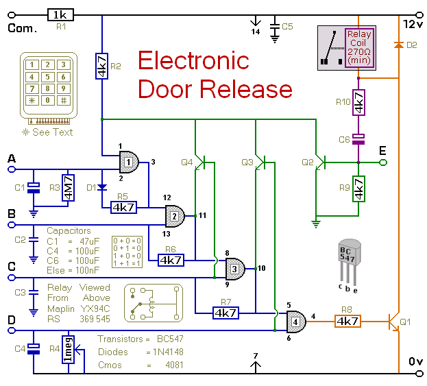
This circuit is designed to operate an electrical door-release mechanism, but it can be utilized for various other applications. Users can enter a four-digit code of their choice, after which the relay will energize for a duration determined by...
It is said that mice are more sensitive to electromagnetic fields, which is why high-voltage grids generally yield poor results in rodent control. The electronic rodent control system described here does not use high-voltage power lines, thus it does...
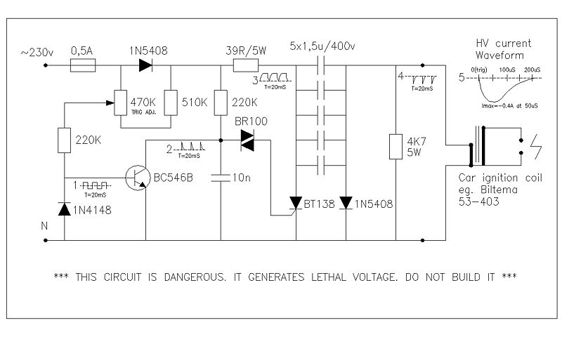
This circuit generates high voltage pulses from a 230 VAC line voltage. The drive end's swing comparator circuit was developed by the creator of this page. The working end is derived from a stroboscope trigger supply circuit. All circuits...
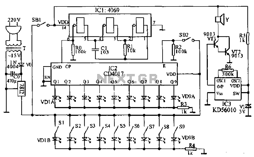
This document presents a principle circuit for electronic games. The main circuit operates in conjunction with the host through the reset button SB2, while the indicators VD1A-VD9A remain off. Prizes, for example, five, are determined by the number of...
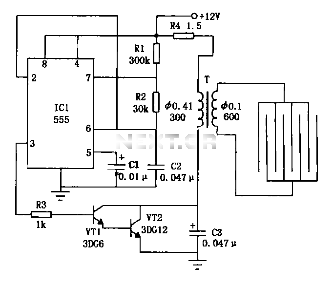
The electronic fly killer employs high voltage applied to a power line pulse to eliminate flies. Utilize the specified website to attract flies effectively. The electronic circuit operates using an integrated circuit (IC) ICL 555, along with resistors R1,...
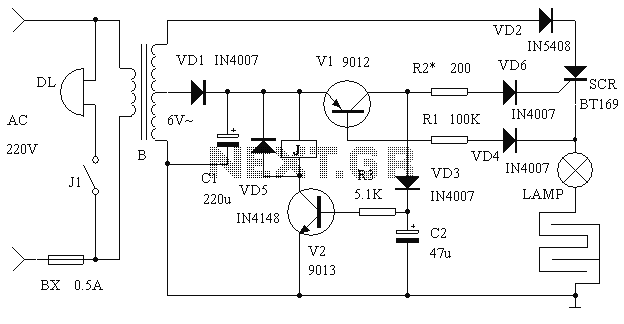
This article presents a driver circuit for a 12V, 5W fluorescent lamp. The circuit utilizes a standard 220V to 10V step-down transformer operated in reverse to achieve a 12V output. The driver circuit for a 12V, 5W fluorescent lamp is...