
ISO120 eight-channel isolated and PWS740 0 ~ 20mA current loop circuit diagram

The eight-channel isolation circuit utilizes the ISO120 isolation amplifier to achieve high-performance signal isolation. The ISO120 is designed to provide electrical isolation between its input and output, effectively preventing ground loops and minimizing noise interference. This is particularly beneficial in industrial applications where different ground potentials may exist.
The PWS740 isolated power supply is employed to power the ISO120, ensuring that the power supply for the input and output sections remains isolated. This isolation is critical in maintaining signal integrity and protecting sensitive components from voltage spikes or noise from other parts of the system.
The VN2222 transistor serves as a current driver, converting the voltage signal from the input (0 to 5V) into a proportional current output (0 to 20 mA). This output is suitable for driving various loads, such as sensors or actuators in control systems. The design allows for scalability, enabling the addition of more channels as needed without compromising performance.
In summary, the combination of the ISO120 isolation amplifier, the PWS740 isolated power supply, and the VN2222 current driver forms a robust eight-channel isolation circuit that excels in environments where signal integrity and noise resistance are paramount. The complete isolation of input and output ensures reliable operation in diverse applications.Eight-channel isolated as shown in Fig constituted by ISO120 and PWS740 0 ~ 20mA current loop circuit. FIG drawn only one channel, circuit 0 ~ 5V input voltage into a current o utput generated by the VN2222 tube drive 0 ~ 20mA current to the load RL. Because the use of isolation amplifier ISO120 with isolated power supplies with PWS740, signals, power and ground to the output signal input signal, power and ground completely isolated, so excellent anti-jamming performance of the circuit.
Related Circuits

A gyrator is a circuit that utilizes active devices and transistors to emulate an inductor. In this instance, the gyrator comprises a transistor in conjunction with resistors R1, R3, and capacitor C2. Alternatively, a unity gain operational amplifier could...
To charge lead-acid batteries, a circuit can be utilized that consists of a current-limited power supply and a flyback converter topology. The circuit designed for charging lead-acid batteries incorporates a current-limited power supply alongside a flyback converter topology to...
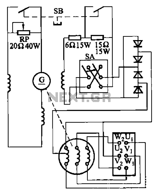
The AX3-300-2 DC arc welding machine circuit is part of the AX, AX1, AX3, and AR series of rotary DC arc welding machines. These machines share a similar structural design, featuring a three-integral unit configuration that combines an inverter...

Figure 4-12 illustrates a five-speed tone selector schematic, which includes circuit components such as IC1, an electromagnetic phono equalizer amplifier, and external RC components. The schematic also features a selection switch for the tone control circuit. When the straight...
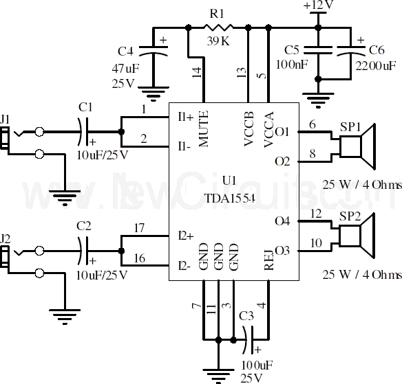
This document presents a 22-watt stereo audio power amplifier circuit diagram utilizing the TDA1554 integrated circuit from NXP Semiconductors (formerly known as PHILIPS Semiconductors). The circuit is designed to amplify stereo signals effectively. It dissipates approximately 28 watts of...
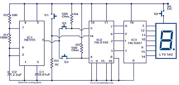
A scoring game circuit is explained with a circuit diagram and circuit parts. The scoring game circuit is designed to track and display scores in a gaming environment. The primary components of this circuit typically include a microcontroller, a score...