
water level indicator circuit schematic

The described circuit functions as a water level detection system using a combination of integrated circuits and discrete components. The primary component, IC1, is a multi-functional integrated circuit that serves as a sensor and controller for the system. The steel rods act as probes to detect the water level; when the water level is insufficient, the rods remain isolated, preventing current flow in the circuit.
The circuit operates under the principle of a window comparator, utilizing IC2A and IC2B. This configuration allows the system to monitor voltage levels at specific points. The output of this comparator is linked to transistor Q1, which is responsible for driving the indicator LED, D3. When the water level is low, the lack of voltage at input pins #2 and #5 of IC2 results in the illumination of D3, providing a visual alert of the low water condition.
As the water level rises and makes contact with the first rod, the electrical connection alters the state of IC1. The input pins #9 to #12 of IC1, which were previously grounded, receive a positive voltage due to the conductive nature of water. This change causes pin #13 of IC1 to go high, signaling a change in the circuit's state, which can be used to trigger additional actions, such as activating a pump or sending a signal to a control system.
The inclusion of resistor R5 serves as a current-limiting component, ensuring that the circuit operates safely without excessive current flow that could damage sensitive components. The insulated wooden board provides necessary separation between the rods and the metal can, preventing unintended short circuits and ensuring reliable operation.
Overall, this water level detection circuit is a practical solution for applications requiring monitoring of liquid levels, utilizing simple yet effective electronic components to achieve reliable performance.When the water-level is below the steel rods, no contact is occurring from the metal can and the rods, which are supported by a small insulated (wooden) board. The small circuit built around IC1 draws no current and therefore no voltage drop is generated across R5.
IC2A, IC2B and Q1 are wired as a window comparator and, as there is zero voltage at input pins #2 and #5, D3 will illuminate. When the water comes in contact with the first rod, pin #13 of IC1 will go high, as its input pins #9 to #12 were shorted to negative by means of the water contact..
🔗 External reference
Related Circuits
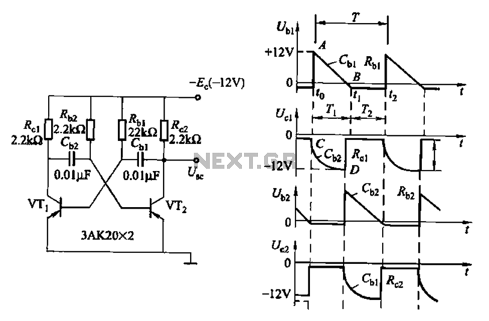
Also known as a no-shot multivibrator, this circuit is often utilized as a pulse (square wave) signal source. The astable flip-flop functions as a strong positive feedback amplifier, with its two branches coupled by an RC timing circuit, resulting...
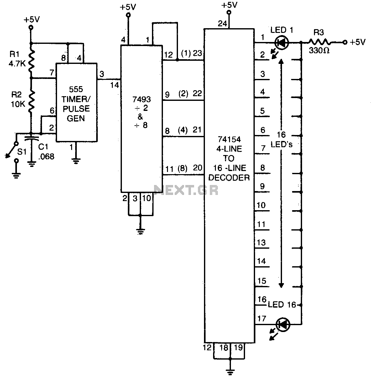
The 555 timer generates a rapid series of pulses when switch SI is in the open position. These pulses are grouped into sets of 16 and converted into binary format by the 7493 counter. The binary output is then...
The 22-watt amplifier is straightforward to construct and cost-effective. This circuit can serve as a booster in a car audio system, an amplifier for satellite speakers in a surround sound or home theater setup, or as an amplifier for...

A simple frequency meter or frequency counter circuit featuring an LCD display and an AVR microcontroller. This includes a DIY schematic circuit diagram and embedded C code. The frequency meter circuit is designed to measure the frequency of input signals...
The figures (a) and (b) illustrate AC measuring circuits. Figure 21(a) presents a current measuring schematic diagram utilizing a magnetic balanced mode Hall device. When the magnetic field generated by the measured current, denoted as IN, is B1, this...
This decibel meter circuit responds to sound pressure levels ranging from approximately 60 to 70 dB (decibels). The sound is captured by an 8-ohm speaker and amplified using a transistor stage along with an LM324 operational amplifier section. A...