
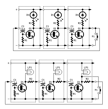
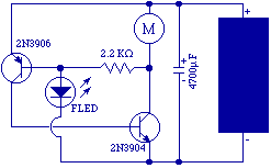
Fake Alarming LED Flasher

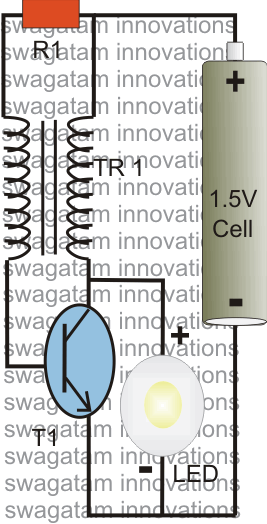
The circuit described utilizes a Joule-thief topology, which is an efficient method for boosting low voltage supplies to a higher voltage suitable for powering devices such as LEDs. The primary component, T1, is a transformer that plays a crucial role in the oscillation process, allowing for energy transfer from the low voltage supply (1.2V) to the LED, which requires a higher voltage (3.5V) to operate effectively.
Capacitor C1 serves to stabilize the output voltage by extending the charge and discharge cycles, thereby enhancing the overall brightness of the LED and improving energy efficiency. The timing components, consisting of resistor R and diode D1, create a feedback mechanism that regulates the charging of capacitor C. As C charges, its voltage rises until it reaches a threshold that forward-biases D1, allowing current to flow and turning transistor Q1 on. This action energizes the LED, causing it to illuminate.
Once the capacitor C discharges sufficiently, the voltage drops below the threshold needed to keep D1 forward-biased, resulting in Q1 turning off and the LED extinguishing. The resistor R then allows capacitor C to recharge from the supply voltage, thus repeating the cycle. The described timing interval of approximately 1 second per flash can be adjusted by changing the values of R and C, allowing for customization of the flashing frequency based on application requirements. This circuit exemplifies a practical application of basic electronic components to achieve efficient power management and control in low-voltage applications.The parts to the right of T1 form a simple Joule-thief ('Blocking' oscillator) circuit which boosts the 1.2v supply to 3.5v to operate the LED. C1 is used to extend the charge and discharge cycles to increase brightness and efficiency. Components R, C and D1 form a simple timing circuit which, with the values shown, is about 1 sec per flash.
Capacitor C charges up through resistor R until its voltage is enough to bias D1 and turn Q1 on to light up the LED. The charge on C is slowly drained, until it is no longer able to keep Q1 on, at which point the LED turns off until C can be recharged by R again.
🔗 External reference
Related Circuits
A voltage supply ranging from 6 V to 15 V is required when using a single LED per module. An increase in the number of LEDs necessitates a corresponding increase in the voltage supply, with additional LEDs connected in...
The post explains a simple 1 watt LED driver circuit using a single 1.5 V penlight cell through the joule thief concept. The coil may be wound over a T13 toroidal ferrite core using 0.2 mm or 0.3 mm...
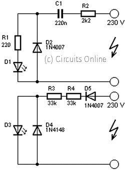
This circuit is used to power an LED with a voltage of 230V. The 230V must be reduced to meet the LED's voltage requirements. To achieve this, a circuit is necessary as described below. The circuit designed to power an...
The project utilizes a 10 x 20 grid of RGB LEDs controlled by the myRIO. It is operated through a web interface on any device that supports WebSockets. Originally, the system was built using an Arduino, but the creator...
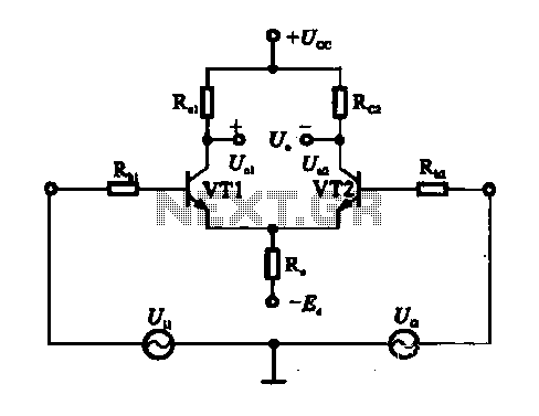
An emitter-coupled differential amplifier circuit is designed to suppress zero drift through circuit symmetry. The effectiveness of zero drift suppression improves with better symmetry; however, in practice, achieving complete symmetry is not feasible. Consequently, the basic differential amplifier circuit...
The original FLED-based SE uses a flashing LED to drive a type 1 solar engine (you'll note that it's just like the Zener-based SE, but with a FLED in the starring role). The good news is that all the...