
FET Based Phase Shift Oscillator

The Wien bridge oscillator is a type of electronic oscillator that generates sine waves. It employs a bridge circuit consisting of resistors and capacitors, with the addition of a variable resistor to maintain oscillation. In this case, the use of Field Effect Transistors (FETs) provides high input impedance, which is beneficial for minimizing loading effects on the circuit.
To design a FET-based Wien bridge oscillator, the following components and steps are typically involved:
1. **Circuit Configuration**: The basic configuration includes two resistors (R1 and R2) and two capacitors (C1 and C2) arranged in a bridge format. The FET will be used as an amplifier to provide the necessary gain for oscillation.
2. **Component Values**: The frequency of oscillation can be determined using the formula:
\[
f = \frac{1}{2\pi R_{1}C_{1}}
\]
where R1 and C1 are the resistive and capacitive components in the feedback loop. The values of R2 and C2 should be selected to match R1 and C1 for balanced conditions.
3. **Gain Adjustment**: A variable resistor (potentiometer) is typically included in the circuit to adjust the gain of the amplifier. This adjustment is critical for starting and maintaining oscillation, as the gain must be slightly greater than one for oscillation to initiate.
4. **FET Selection**: The choice of FET is important; it should have low noise characteristics and high transconductance to ensure stable oscillations. Commonly used FETs include the JFET or MOSFET types.
5. **Simulation in PSpice**: After designing the circuit, it can be simulated using PSpice. The simulation should include the FET model, along with the resistors and capacitors. It is essential to analyze the transient response to confirm that the circuit oscillates at the desired frequency and amplitude.
6. **Output**: The output can be taken from the junction of the resistors and capacitors in the bridge. This output can be connected to further stages for amplification or processing, depending on the application.
In conclusion, the FET-based Wien bridge oscillator is a versatile circuit for generating sine waves, and careful consideration of component values and configurations will ensure successful operation. Simulation tools like PSpice provide valuable insights during the design process, allowing for adjustments before physical implementation.Hi I need help with design of a FET based wien bridge oscillator and simulate it using pspice. Any suggestion?.. 🔗 External reference
Related Circuits
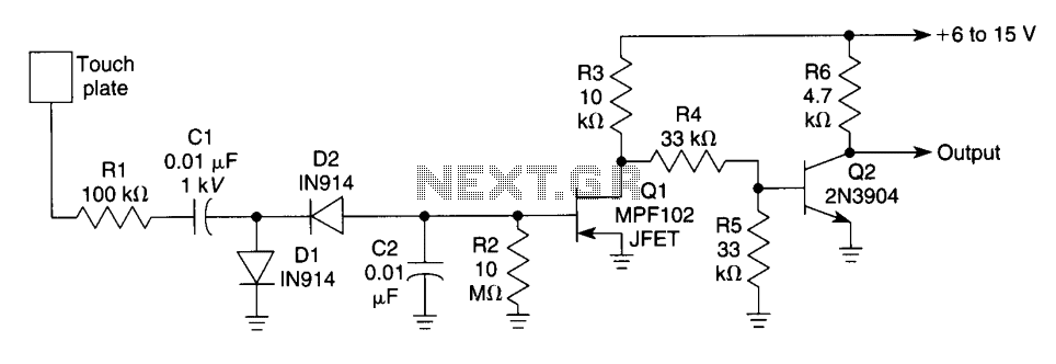
When the touch plate is activated by a large object, such as a human body, stray 60 Hz pickup is rectified by diodes D1 and D2, resulting in a negative voltage across resistor R2 and capacitor C2, which affects...
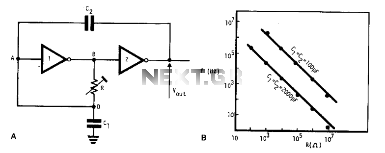
This simple, low-cost oscillator is constructed using two CMOS buffer inverters, two capacitors, and a variable resistor. The circuit operates with voltage levels ranging from 4 V to 18 V. When C1 equals C2, the frequency of oscillation is...
The following circuit illustrates how to build a variable DC power supply circuit. This circuit is based on the 7805 IC. Features: other output is ... The variable DC power supply circuit utilizing the 7805 integrated circuit (IC) is designed...
A simple network design is a key feature of the Pierce circuit, as illustrated by these 1-MHz oscillators. Operating the crystal slightly above resonance requires only one high-gain transistor stage. Operating it exactly at series resonance requires an additional...
A 50 kHz circuit is feasible due to its nearly ideal characteristics. The 50 kHz circuit is designed to operate effectively within that frequency range, leveraging components that exhibit minimal parasitic effects and optimal linearity. The circuit may include...
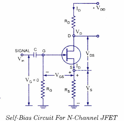
Unlike BJTs, thermal runaway does not occur with FETs. However, the significant differences in maximum and minimum transfer characteristics make ID levels unpredictable with a simple fixed-gate bias voltage. To achieve reasonable limits on quiescent drain currents (ID) and...