
fez accutest circuit

The battery tester circuit is engineered to evaluate the performance and capacity of various battery types, providing accurate and reliable data storage via a microSD card. The core components of the circuit include a microcontroller, an analog-to-digital converter (ADC), a voltage divider, and a microSD card module.
The microcontroller serves as the central processing unit, controlling the operation of the tester and managing data acquisition. It is programmed to initiate the testing sequence, read voltage levels from the battery under test, and process the data for characterization. The ADC is utilized to convert the analog voltage readings from the battery into digital values that the microcontroller can interpret.
A voltage divider circuit is employed to scale the battery voltage to a level within the acceptable range for the ADC. This ensures that the microcontroller receives accurate voltage readings, which are critical for determining the battery's state of charge and overall health.
The microSD card module is interfaced with the microcontroller to facilitate data storage. Once the battery testing is complete, the results, including voltage levels and any other relevant metrics, are written to the microSD card in a structured format. This allows for easy retrieval and analysis of the battery performance data.
Power supply considerations for the circuit include the use of a regulated power source to ensure stable operation of the microcontroller and other components. Additionally, proper filtering and decoupling capacitors should be implemented to minimize noise and enhance the reliability of the measurements.
Overall, this battery tester circuit is designed to provide a comprehensive solution for battery characterization, with an emphasis on accurate data collection and ease of use through the integration of a microSD card for data storage.This page describes a battery tester I designed. It will characterize your batteries and save the results on an microSD card.. 🔗 External reference
Related Circuits
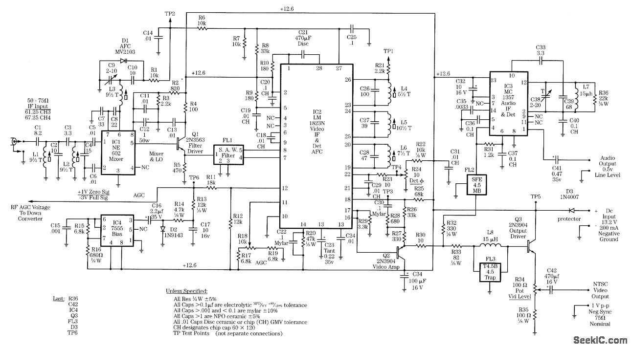
Radio-frequency schematics (also see NE602 datasheet and application note). This page contains electronic circuits related to RF receivers. This index features a broad collection of RF receiver circuits. Radio-frequency (RF) schematics are essential for designing and implementing circuits that operate...
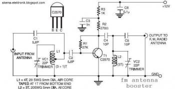
The input coil L1 is composed of four turns of 20 SWG enamelled copper wire, wound slightly spaced over a 5 mm diameter former. It is tapped at the first turn from the ground lead side. Coil L2 is...
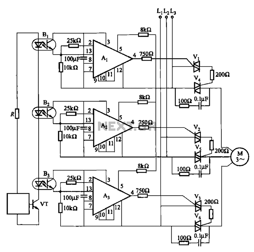
The 331 circuit depicted in the figure utilizes a two-way thyristor for controlling the start and stop functions of a motor. It operates without mechanical contacts, generating no noise or sparks, making it suitable for applications that require frequent...
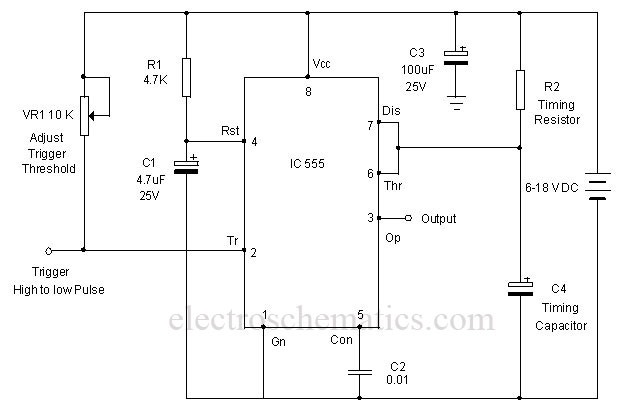
A monostable multivibrator using the IC CD4538 is a precision device that functions as a monostable/astable multivibrator and is designed to avoid false triggering. This IC is suitable for various applications requiring precise timing cycles. The CD4538 offers improved...
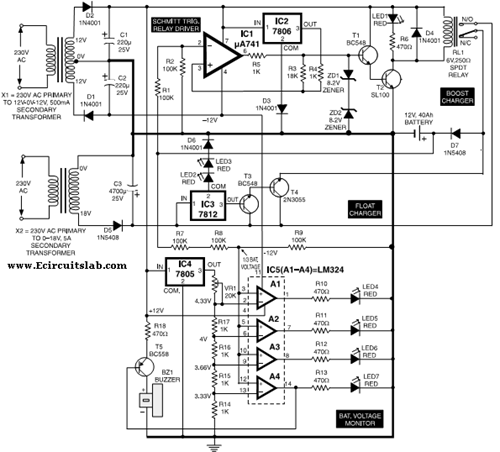
This circuit illustrates the use of the 7806 IC in an automatic battery charger circuit diagram. It is designed for a car battery with an approximate rating of 40 Ah. The automatic battery charger circuit utilizing the 7806 integrated circuit...
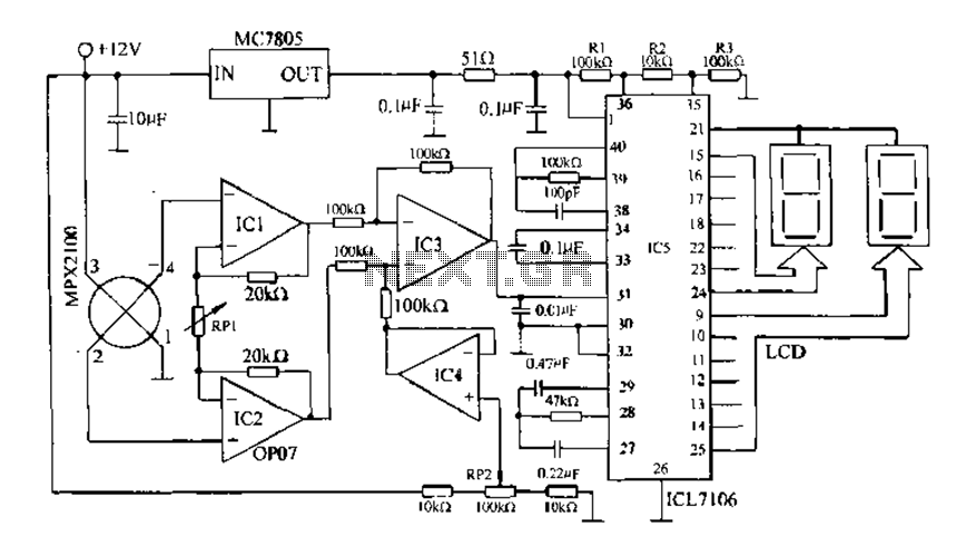
Digital pressure measuring circuit using AD7710/7715/7730 multifunction digital sensor signal conditioning ICs. These ICs integrate a digital interface with the control port, a clock generator, a digital filter, amplitude modulation, a programmable gain amplifier, an A/D converter, and other...