
Field-strength meter

The described antenna system employs a compact design, utilizing insulated stranded wire approximately 20 cm in length. This wire is strategically arranged within a small plastic enclosure, which serves both to protect the antenna and to facilitate its installation. The choice of insulated stranded wire ensures flexibility and durability, making it suitable for various applications.
The RF current generated by the antenna is processed through a rectification stage involving two diodes. This configuration allows for the conversion of alternating current (AC) signals into direct current (DC), which is essential for further signal processing or measurement. The selection of diodes is critical; they should be chosen based on their forward voltage drop, reverse recovery time, and maximum current rating to ensure efficient rectification.
To provide adjustable output for measurement purposes, a 10 k potentiometer is integrated into the circuit. This component allows for variable attenuation, enabling the user to fine-tune the signal level before it is presented to the meter. The potentiometer's resistance value is suitable for applications where moderate signal levels are encountered, and it allows for a significant range of adjustment to accommodate varying input signal strengths.
Overall, this antenna system is designed for effective RF signal reception and measurement, with a focus on compactness and user adjustability. The combination of the antenna design, rectification stage, and attenuation control creates a versatile tool for various electronic applications.The antenna consists of about 20 cm of insulated stranded wire glued or taped around the inside of a small plastic box. RF current is rectified by two diodes, and a 10 k potentiometer provides variable attenuation for the meter.
Related Circuits
This digital alarm speedometer circuit allows for the measurement of the acceleration of any moving object, particularly cars and other vehicles. The acceleration is displayed in kilometers per hour (KPH) with a three-digit display. The system operates using laser...
A digital voltmeter, or any voltmeter with millivolt resolution and high input impedance, can be utilized as a temperature-to-voltage adapter. The described temperature-to-voltage adapter is designed to convert temperature readings into corresponding voltage outputs, suitable for interfacing with digital voltmeters....
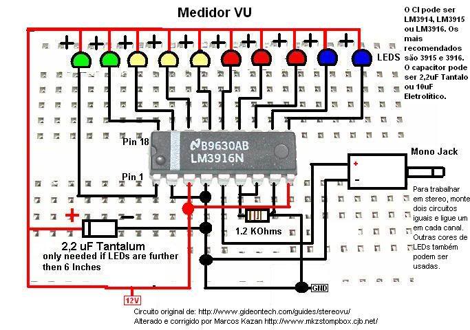
A post related to a do-it-yourself project for creating a VU meter and homemade rhythm lights that are easy to assemble. The project involves designing and constructing a visual audio level meter (VU meter) that responds to sound levels, as...
An analog meter typically does not exhibit high impedance due to the absence of a buffer circuit within its design. By incorporating active buffering, the input impedance of this circuit can be significantly enhanced. The integration of an active buffer...

The schematic for this tutorial is straightforward. It involves connecting the ADXL320 sensor to the PIC microcontroller and an LED. The power supply is assumed to be a +5V battery to power the PIC. A custom power circuit can...
The circuit is designed to operate with an audio power amplifier that uses 18V-0V-18V power rails. The specific voltage is not critical, but the feedback is referenced to an LED chain connected to a 12V rail, necessitating a separate...