
Filament and Control Power Supplies
The circuit described integrates various components to ensure the safe and efficient operation of an amplifier. The AC power supply is managed through a series of fuses and switches, providing not only functionality but also safety against electrical faults. The use of a filament transformer (T1) to supply power to most tubes highlights the design's focus on ensuring that the necessary voltage levels are maintained for optimal performance. The inclusion of a hum balance potentiometer (R1) reflects an understanding of the potential noise issues in audio applications, even if its impact may be limited.
The timer relay (RLY1) serves a critical role by introducing a delay that allows filaments to warm up, thereby enhancing the reliability of the amplifier's operation. The safety link associated with the gas regulator (V4) indicates a thoughtful approach to preventing damage during operation, particularly if components are inadvertently removed. The design also effectively employs LED arrays (D3 and D4) for visual feedback, enhancing user experience while maintaining safety through current-limiting resistors.
The use of a relay (RLY2) to manage the speaker output during power-up is a prudent design choice that mitigates the risk of audible transients, thereby preserving audio quality. Additionally, the incorporation of a fan (MOT1) for cooling under the chassis is indicative of a comprehensive thermal management strategy, ensuring that the amplifier operates within safe temperature limits, thus prolonging the lifespan of its components. Overall, the schematic reflects a well-considered approach to amplifier design, balancing performance, safety, and user experience.AC power is supplied via AC Fuse F1 and Power On/Off switch S1 to 6. 3V filament transformer T1. Fuse F2 is provided as an additional safety feature, since a short to the filament transformer may not be enough to blow the main power fuse. Hum balance pot R1 is provided for good measure, though it`s unlikely to have much of an effect given the overa
ll design of the amplifier. This supplies filament power to most of the tubes in the unit, as well as the #47 pilot light I1. Note that T1 does not provide filament power for tubes V1, V3, V4 and V18. V4 is a gas regulator tube, and obviously doesn`t need filament voltage. V1 and V3 are in the high-voltage regulator circuitry, and require isolated filament supplies because their cathodes are sitting at high voltage above ground; these will be covered in the HT section. V18, the first gain-stage input pentode, is treated specially to a DC supply (covered in the below) to reduce the possibility of filament-induced hum.
D1 and R2 provide rectification and current limiting for metering the supply voltage. Note that in all schematics, "MP" represents a metering point; the metering circuit is further detailed in next section. Switched AC voltage is also applied to a timer relay RLY1. I used a commercial timer block for a standard octal relay, by Releco; this is rather pricey, however, and DIY timer circuits are readily available if you search the web.
This timer delays for a variable time (on the order of 20 seconds) to allow all the important filaments to reach full temperature before energizing the main HT supply. The input to the timer relay is also routed through the "safety link" incorporated in gas regulator V4 (pins 3 and 7), preventing energizing of the HT supply (and very probable damage) if the unit is powered up with the regulator removed.
This timed AC is also applied to 12-volt control transformer T2, the output of which is rectified by full-wave bridge rectifier D2, and filtered by capacitor C1. This DC voltage powers red and blue LED arrays D3 and D4 built into the meter housing; it`s quite the effect when the HT circuit kicks in, and the meter lights up.
Dropping resistor R3, in conjunction with R4 and R5 (chosen as appropriate for the LED arrays) limit the current through the LEDs to a safe value. This DC voltage is further filtered and dropped to 6. 3 volts by the network consisting of R6 and C3, providing filament power for the 6K7 input pentode V18.
The DC voltage is also applied to a small 12V relay, RLY2 via R7 and C2. Its contacts are in series with the main speaker output line. This causes a slight (about 1/2 second) delay after energizing the HT supply, avoiding the pop or snap that could otherwise result as the amplifier stabilizes. During the time it takes the relay to engage, the contacts connect to a small dummy-load resistor to prevent transients from being reflected back to the output tubes.
Finally, the DC voltage is used to energize a small DC fan, MOT1 which helps to keep the components under the chassis cool. The top-side components (tubes and transformers) will generally get enough cooling by convection, but the underside components can use some help.
A small fan is cheap insurance in this respect. 🔗 External reference
Related Circuits
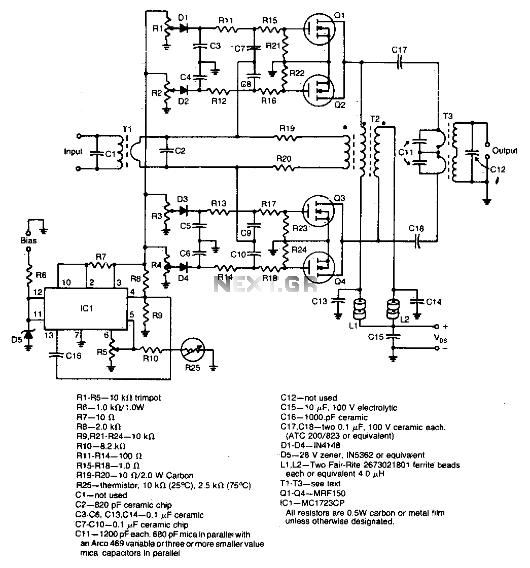
A unique push-pull parallel circuit utilizes four MRF150 RF power FETs connected in parallel at relatively high power levels. Supply voltages ranging from 40 to 50 Vdc can be employed, contingent on the linearity requirements. The bias for each...
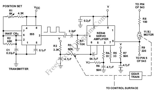
This is a servo system controller circuit designed for remote control of a servo motor. The circuit utilizes a 555 timer and requires only six additional components. The servo system controller circuit operates by generating a pulse-width modulation (PWM) signal,...
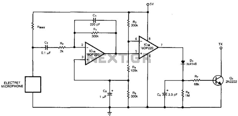
An electret microphone feeds a bandpass filter circuit (IC1A), which subsequently drives a comparator. This comparator activates Q1, a switch that conducts when audio signals from IC1B cause D1, C4, R6, and R7 to bias it ON. The circuit begins...
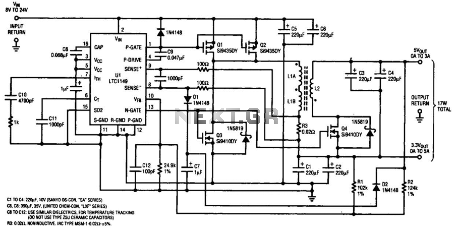
One LTC 1149 synchronous switching regulator can deliver both 3.3 and 5 V outputs. The design's simplicity, low cost, and high efficiency make it a strong contender for portable, battery-powered applications. The circuit described accepts input voltages from 8...
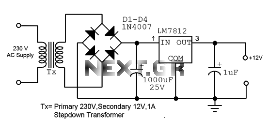
This is a straightforward 12V power supply circuit diagram. It features a fixed voltage output and is based on the LM7812 voltage regulator integrated circuit. The 12V power supply circuit utilizing the LM7812 voltage regulator is designed to provide a...
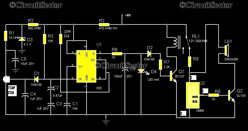
Numerous circuits are available for infrared burglar alarms; however, the transmitter section of these circuits can be complex and may require assembly. This burglar alarm circuit utilizes a standard DVD remote as the transmitter, which reduces both cost and...
Warning: include(partials/cookie-banner.php): Failed to open stream: Permission denied in /var/www/html/nextgr/view-circuit.php on line 713
Warning: include(): Failed opening 'partials/cookie-banner.php' for inclusion (include_path='.:/usr/share/php') in /var/www/html/nextgr/view-circuit.php on line 713