
Five reversing operation of the reverse brake circuit

The automatic round-trip plug braking circuit is designed to enhance safety and reliability in applications where precise control of electrical devices is essential. This circuit ensures that the operation of the primary switches (SQ1 and SQ2) is safeguarded against unintended disconnections or faults that may arise during operation.
In this design, the primary switches are critical for controlling the flow of electrical current. However, to mitigate the risk of accidental activation or failure, the inclusion of limit switches S03 and S04 serves as an additional layer of protection. These limit switches are strategically positioned to monitor the operational state of the primary switches. If either switch SQ1 or SQ2 experiences a fault condition, the limit switches will activate and interrupt the circuit, thereby preventing potential hazards.
The circuit operates by using a combination of relays and limit switches that are interconnected in a manner that allows for automatic resetting after a fault condition has been cleared. This functionality is crucial in applications where continuous operation is necessary, and any downtime must be minimized.
The overall design emphasizes robustness and safety, ensuring that the circuit can handle unexpected conditions without compromising the integrity of the system. The use of additional protection limit switches not only enhances the reliability of the circuit but also increases the overall lifespan of the components involved, making it a suitable choice for various industrial applications. Circuit shown in Figure 3-132. The line is automatically round-trip, plug braking circuit. In order to prevent or limit switch SQl offside SQz malfunction caused the accident, two increased protection limit switches s03 and s04.
Related Circuits
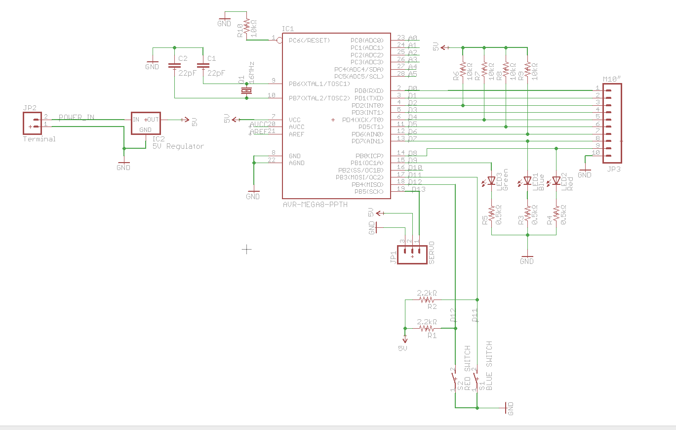
A circuit utilizes a keypad, a servo, and several LEDs, connected to an Arduino Uno. The objective was to integrate all components onto a single PCB, effectively creating a custom version of the Arduino. Upon startup, the red LED...

Robot eyes circuit of Service. A simple circuit to simulate a man appointed to it. It consists of a dual-lamp working in an unsteady manner. Circuit diagram. The robot eyes circuit is designed to create a visual effect that simulates...

The search coil, CI and C2, form a tuned circuit for the oscillator, which is tuned near the center of the broadcast band. Tune a portable radio to a station near the middle of the band, then adjust C2...
As a cyclist, there is a constant search for methods to enhance visibility during nighttime rides. The concept of the `NITE-RIDER` was developed to create a distinctive and attention-grabbing rear light for bicycles. This design features nine extra-bright LEDs...

The circuit for bridge measurements is straightforward, as illustrated in the figure. The sensor bridge drive voltage can be adjusted between +4V and +10V, depending on the specific requirements of the sensor. Two fixed gain options of 333.3 and...

This circuit illustrates a 3A Switching Regulator Circuit based on the LM317K integrated circuit. It is designed to be simple and cost-effective. The 3A Switching Regulator Circuit utilizing the LM317K IC serves as a versatile voltage regulation solution, capable of...