
Float Charger For NiMH Cells

The LM317 voltage regulator circuit is designed to provide a stable output voltage suitable for charging NiMH batteries. The circuit's resilience against fluctuations in load, supply voltage, and temperature is crucial for maintaining battery health and performance. In float charging applications, this stability ensures that the batteries remain fully charged without the risk of overcharging, which can lead to reduced battery life or damage.
The configuration of resistors R2 and R3, along with the adjustable trimpot VR1, allows for precise voltage output control. The fixed resistor R2 is set at 240 ohms, while VR1 is adjusted to achieve the desired output voltage of 1.35V per cell. This adaptability is essential, as different battery chemistries and configurations may require slight adjustments in charging voltage to optimize performance.
The inclusion of diode D1 is a critical safety feature, preventing reverse polarity that could damage the regulator and the connected batteries. The current limiting feature provided by resistor RCL and transistor Q1 adds another layer of protection, ensuring that the circuit can handle unexpected conditions, such as short circuits or the connection of deeply discharged batteries, without failure.
LED indicators serve a dual purpose in this circuit: they provide visual feedback regarding the operational status of the charger and help ensure that the regulator operates within safe limits. The minimum load provided by LED1 and its associated resistor is particularly important as it prevents the output voltage from drifting upward when the battery is nearing full charge, which could otherwise lead to overvoltage conditions.
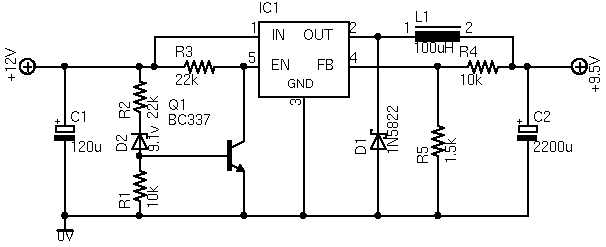
The design accommodates various configurations, allowing for the charging of multiple batteries in series with peak currents tailored to the specific application. The heat management considerations outlined for the TO-220 and TO-3 packages are essential for ensuring reliable operation, particularly under higher load conditions. Proper thermal management is vital in maintaining the longevity and reliability of the LM317 regulator in various charging scenarios.Although not a new device, the LM317 is still a high-performance regulator. Its output voltage is essentially immune to fluctuations in load, supply voltage and temperature and this makes it ideal as the central element in a float charger for NiMH cells. Float charging has the advantage of keeping the cells fully charged and ready to use without t he potential damage of long-term trickle charging or the cost of low-discharge cells. This works because NiMH cells do not have the memory problems associated with Nicads. The circuit is based on a conventional LM317 regulator. Resistors R2 & R3 and trimpot VR1 set the maximum output voltage to between 1. 3V and 1. 4V per cell. VR1 should be adjusted for a value of 1. 35V per cell at the regulator output. Resistor R2 has been fixed at 240O. The formula for the voltage output is: Vout = 1. 25*(1 + (R3 + VR1)/R2). Diode D1 protects the circuit against reverse polarity of the power supply and protects the LM317 should the power be disconnected while it is still connected to a charged battery pack. Resistor RCL and transistor Q1 limit the maximum current in the event of a short circuit or the connection of a severely discharged battery pack.
LED2 provides an indication of voltage input to the charger. LED1 and the 680O resistor provide the same function for the charger output and also provide a minimum load for the regulator when the battery pack is nearing full charge. This is necessary to keep the regulator output from drifting up and damaging the batteries. The circuit uses an external DC plugpack and is suitable for four NiMH cells rated at 2. 5Ah. Table 1 gives alternative values for 1-10 batteries in series at peak charge currents of between 200mA to 600mA.
If you are using the specified plug-pack and the TO-220 packaged LM317T, you will need a heatsink rated at 12 °C/W or better for any design other than the 200mA single cell charger. A TO-3 packaged device with the correct plug-pack will be OK without a heat-sink for any of the 200mA configurations and up to four cells charging at 400mA.
🔗 External reference
Related Circuits
The ASUS Eee is an ultra-portable notebook designed for tech enthusiasts, offering essential features without unnecessary extras. It boasts excellent build quality and is competitively priced. In New Zealand, it can be purchased exclusively from DSE, making it cost-effective...
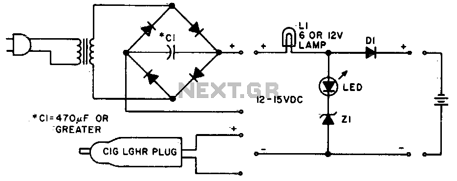
Lamp LI will glow brightly while the LED remains off when the battery is low and charging. Conversely, the LED will illuminate brightly, and the light bulb will be dim when the battery is nearly charged. Lamp LI should...
This simple charger uses a single transistor as a constant current source. The voltage across the pair of 1N4148 diodes biases the base of the BD140 medium power transistor. The base-emitter voltage of the transistor and the forward voltage...
With the advent of modern integrated circuits (ICs), sophisticated circuits today are no longer required to be complex and lengthy. The chips themselves contain most of the intricate circuitry built-in and can independently perform the desired functions. For instance,...
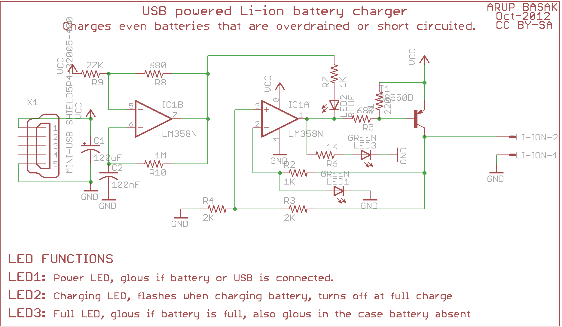
A year ago, a circuit of a USB Li-ion charger based on the LM358 op-amp was shared. The circuit had some issues reported by commentators, including incorrect LED orientation. It is advised not to post email addresses or phone...
Most universal chargers to charge the battery 9 V (8.4 V more). However, while the charging of NiCd or NiMH rechargeable governed by a special circuit or a microprocessor, 9 V batteries are recharged mostly from current sources. I...