
USB li-ion charger revision

The USB Li-ion charger circuit utilizing the LM358 op-amp is designed to charge lithium-ion batteries, particularly the 18650 cells, through a USB interface. The circuit operates by regulating the voltage and current supplied to the battery, ensuring safe and efficient charging. The LM358 op-amp serves as a voltage comparator and controller, maintaining the output voltage at an optimal level for lithium-ion batteries, typically around 4.2V when fully charged.
To address the issues reported, particularly the LED orientation and output current, modifications can be made to the circuit. The output voltage can be increased by ensuring that the feedback loop of the op-amp is correctly configured, allowing for a higher voltage output. If the output is only reaching 3.77V, it may indicate that the op-amp is not being driven correctly or that the power supply voltage is insufficient.
For achieving a charging current of 1 to 1.5 amperes, the circuit can be enhanced by integrating a power transistor, such as the S8550, to handle the higher current demands. The S8550 can be configured as a switch, controlled by the op-amp output, allowing it to drive the load with the necessary current. Additionally, using a Darlington pair like the TIP102 can further amplify the current, ensuring that the circuit can deliver the required charging current to the 18650 cells.
The inclusion of a boost converter, such as the MC34063, is a practical approach to stepping up the voltage from the battery to a usable level for USB devices. This circuit can be configured to increase the voltage from the 3.7V battery to 5.5V, suitable for powering USB devices. The solar panel input can also be integrated into the circuit, allowing for sustainable charging options during sunny conditions.
Overall, careful attention to the configuration and components used in the circuit will ensure that it functions effectively for charging lithium-ion batteries while accommodating the user's requirements for higher current output and versatility in power sources.An year ago, I`ve shared a circuit of USB li-ion charger based on LM358opamp. The circuit had some problems as reported by commentators that inclide wrong direction of LEDs. Don`t post your email or phone number in the comment box. Only put email address in the email field. Comments are moderated so it may take time for them to appear on the site. Offensive comments will be deleted. If this is a request for custom circuit, then use the wish a circuit form. I`ve built your circuit just as you show in your schematic, with the exception that I`m using a barrel jack connector, and a 5V switching power supply purchased from Sparkfun. com. When I test the voltage coming from the part of your circuit that you use to charge the battery, it`s reading 3.
77 Volts is this correct I had a dead` (measure 0V) Nokia 3. 6 battery and the circuit seemed to work. However, when trying to charge a newer Samsung 3. 7V, it doesn`t seem to work. When fully charged, the battery reads 3. 99V. I put it back in the phone until it was about 3/4 full which it then reads 3. 79V. When I connect it to the charger, it doesn`t seem to do anything. Is this because the charger is outputting less voltage (3. 77V) I would like to use full power of s8550, it means a 1, 5 ampere charging current. I have strong 5V power supply, which can deliver about 2A of current. How can I change Your schematic, to obtain current of 1 to 1, 5 ampere I need such a high current, to charge high capacity 18650 Li-Ion cells. Thanks in advance for Your reply. my output power was very low but when i removed LED 1 the voltage a lot more to what i would like. However i am only getting a 80mA out but i would like something a lot higher. I just have a question, i done this circuit on my breadboard, but my exit tension is something like 3, 6v is this normal that`s because the finish led light up until my battery reach 100% of charge.
maybe 30% or 40% I`ve read somewhere on internet that this chargers has a 4, 2v and 10% of the current on output I`m alone-home-learning electronics and hope your help for my project. by the way, my batteries are 2x 3, 7v 3000mah parallel connected. Also would it be plausable to use the pnp to switch on a darlington or other current boosting transistor.
(pnp collector to npn base). Only because the tip 102 darlington is quite common at places like radioshack. I also added a mc34063 simple boost from 3. 7 to 5. 5v to a usb female jack to turn this into a sweet battery backup charger. As well as a 6v solar panel input for sunny days. 🔗 External reference
Related Circuits

This is a simple and low-cost NiCd and NiMH battery charger. The schematic diagram indicates that the charging current (I) should be set to 1/10 of the battery's rated capacity. For instance, if the battery has a rated capacity...
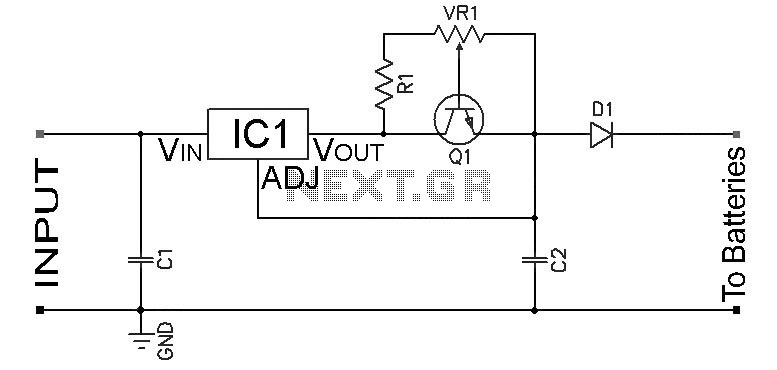
Adjustable Constant Current Ni-Cd and Ni-MH Battery Charger Circuit. This circuit is designed to provide a constant current for charging Ni-MH or Ni-Cd batteries. A schematic diagram of the circuit is available. The adjustable constant current battery charger circuit for...
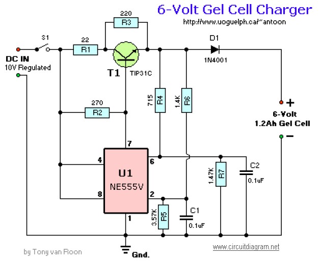
The following diagram illustrates the battery charger schematic for a 6V Gel Cell battery type. Component Parts List: R1 = 22 ohm, 1W; R2 = 270 ohm; R3 = 220 ohm; R4 = 715 ohm, 1%; R5 = 3.57K,...

This circuit is for a temperature controlled constant current battery charger. It works with NICD, NIMH, and other rechargeable cells. The circuit works on the principle that most rechargeable batteries show an increase in temperature when the cells become...
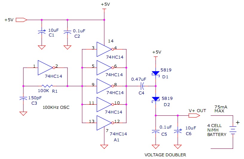
The circuit described will trickle charge a four-cell pack of AA or AAA NiMH batteries. It draws current from the +5V available from a USB connection and supplies approximately 70mA of current to the battery. This current level is...
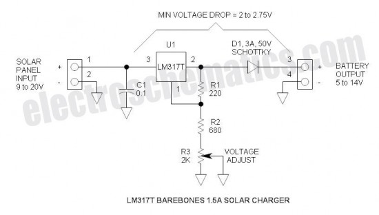
This is the simplest and most affordable solar battery charger that a hobbyist can create. It has some drawbacks compared to other similar controls, but offers unique advantages. The solar battery charger circuit is designed to harness solar energy to...