
FM Radio Jammer With 2N2222 Transistor

The described circuit is designed as a VHF oscillator, primarily using a 2N2222 NPN transistor, which serves as the active amplification component. The circuit operates by generating oscillations in the VHF frequency range, typically between 30 MHz and 300 MHz, which is the standard operational band for FM radio transmissions.
The configuration of the circuit includes a feedback loop that stabilizes the oscillation frequency. The inductor and capacitor form a resonant LC circuit, which determines the oscillation frequency. The resistor is used to set the biasing conditions of the transistor, ensuring it operates in the active region for optimal performance.
Power for the circuit is supplied by a battery, which provides the necessary voltage and current for the transistor to function effectively. The output of the oscillator is coupled to the antenna, which radiates the VHF signals. These signals interfere with nearby FM radio frequencies, effectively jamming the reception of legitimate broadcasts.
Due to the nature of this circuit, it is important to note that the use of jamming devices may be illegal in many jurisdictions, as they can disrupt legitimate communications and violate regulations set forth by telecommunications authorities. Therefore, this circuit should be used with caution and awareness of local laws regarding radio frequency interference.This Circuit can be used to jam FM radios in its vicinity. This is a classic single transistor oscillator operating in the VHF region. Working principle of the circuit is very simple and straight forward. Powerful VHF oscillations from the circuit will interfere with the FM signals to nullify it. Component: 2N2222 Transistor, Resistor , Capacitor, Battery, Inductor. [circuitstoday. com] 🔗 External reference
Related Circuits
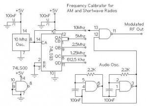
The following circuit illustrates an AM/Shortwave Radio Frequency Calibrator Circuit Diagram. This circuit is based on the 74LS93 IC. Features: The .. The AM/Shortwave Radio Frequency Calibrator Circuit utilizes the 74LS93 integrated circuit, which is a 4-bit binary counter. This...
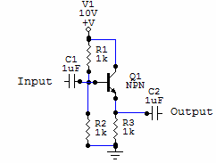
Two examples of the most common types of Voltage followers (buffers). You can find some theory behind them in our amplifier gain and buffer amplifier pages. This first circuit is a very simple one transistor voltage follower. Consists of...
A regenerative radio receiver is known for its simplicity, weak signal reception, inherent noise-limiting and automatic gain control (AGC) action, as well as its immunity to overloading and spurious responses. The regenerative radio receiver, often referred to as "regen,"...
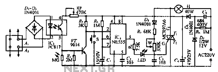
The Ai. A2 series operates with a telephone line, where sound anomalies or off-hook currents activate a light within an arc tube, which in turn triggers a photosensitive MOSFET. This process involves a saturated conduction base voltage that sends...

This circuit maintains a constant voltage, with an adjustable output voltage. It serves to reduce the input voltage while keeping the voltage constant. The amplifier model used is the Q1 2N3904 in a common-emitter configuration. This configuration allows the...
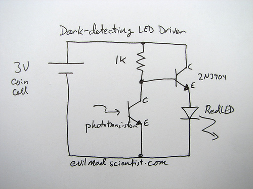
The following circuit illustrates a simple and inexpensive dark-detecting LED circuit. Features include the use of photoresistors, specifically a photocell or LDR, and an LED. This circuit utilizes a light-dependent resistor (LDR) as the primary sensing element. The LDR exhibits...