
FM Wireless Mike

The FM wireless microphone project involves several key components that work together to facilitate effective communication. The dynamic microphone captures audio signals, converting them into small alternating currents. These currents are then amplified by the microphone preamplifier, which utilizes a transistor in voltage divider mode to increase the signal strength before it is sent to the FM transmitter.
The FM transmitter itself is designed as a tuned collector radio frequency oscillator, which is essential for generating the radio waves that carry the audio signal. The parallel tank circuit, composed of a coil and a trimmer capacitor, is critical for determining the resonant frequency of the oscillator. By adjusting the trimmer capacitor, the user can fine-tune the operating frequency to ensure it falls within the standard FM band, allowing compatibility with common FM radios.
When the audio signal from the preamplifier is applied to the base of the transistor in the oscillator, it induces changes in the base-emitter junction voltage. This alteration causes variations in the capacitance at the base, which directly affects the resonant frequency of the tank circuit. As the capacitance changes, the frequency of the transmitted signal shifts accordingly, resulting in frequency modulation of the audio signal.
The final output of this system is broadcasted via a compact radio antenna, enabling the transmission of audio signals over considerable distances. The design emphasizes simplicity and effectiveness, making it an excellent project for those interested in exploring the principles of radio frequency transmission and audio modulation.FM wireless Mike is a small electronic project based on a radio transmitter. It is a wonderful idea to make a wacky talky through which you can talk to your friend, next door. Just speak or play into the microphone and you ’ll broadcast to an FM receiver at distances up to 50 feet (maybe 100 feet if the wind is right). Use a standard FM radio to r eceive the sound. Microphone Preamplifier is a simple audio amplifier. Transistor Q1 is operated in Voltage Divider Mode. We use a dynamic microphone in the amplifier. The small alternating current produced in the microphone is amplified and fed in to the FM transmitter. FM transmitter is a tuned collector radio frequency oscillator. The coil and trimmer is in parallel tank circuit. We specify the value of trimmer and size of the coil such that the resonant frequency will be near 88-108 MHz (in the FM radio Band).
The oscillator oscillates with a constant resonant frequency and we can change the operating frequency by changing the trimmer capacitance. This frequency is the center frequency of the FM. If we want the FM as a modulation we have to apply the modulating signal (audio signal from amplifier) to the base of the transistor of the oscillator.
We all know the base-emitter junction acts like a diode. If we apply the signal the voltage across the junction will change and this particular transistor have some property of changing base capacitance according to the applied input voltage. Thus we change the capacitance which is in series with the resonant tank circuit causing a change in operating frequency.
This is actually the FM modulation. Now the modulated signal will be transmitted via a small radio antenna. 🔗 External reference
Related Circuits

Wireless stepper motor speed control project using a laser and IC555. This project provides insights into the fundamentals and circuit construction for controlling the speed of a wireless stepper motor utilizing a laser and the IC 555 timer. The project...
Circuit designed to alleviate concerns related to high frequency utilizes a ready-made module, specifically an Aurel audio FM transmitter. This compact circuit board, measuring 2 cm by 4 cm, supports a modulation frequency track and delivers an RF power...

Typically, home appliances are controlled using switches, sensors, and similar devices. However, physical contact with switches can pose risks, especially in the event of a short circuit. The circuit outlined here eliminates the need for physical contact to operate...
The capability to control lights and fans wirelessly has transitioned from an expensive luxury to widely accessible consumer solutions. Nevertheless, creating a custom solution remains an engaging project for hobbyists and tinkerers. RobotGrrl has developed user-friendly libraries aimed at...
The current system is a dedicated 486 computer running Homeseer software. The hardware setup includes a CM11A computer-to-X10 interface along with several appliance and lamp modules. Additionally, there is a homebrew infrared (IR) system that connects the computer to...
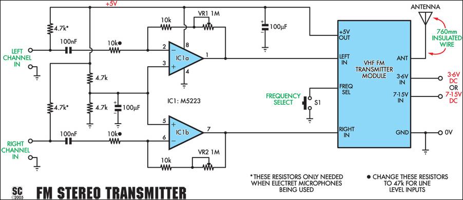
This stereo FM wireless microphone provides a high-quality audio link. Testing demonstrated a reliable performance at distances exceeding 50 meters. While not the first wireless microphone produced, this model stands out due to its stereo capabilities, delivering surprisingly good...