
Fog Lamp Switch Circuit

This circuit design effectively addresses the need for compliance with regulations regarding trailer fog lights while ensuring functionality and safety. The use of a relay allows for the automatic disconnection of the vehicle's rear fog light when a trailer is connected, preventing confusion and enhancing visibility for other drivers. The inclusion of a reed contact as a sensing element provides a reliable means of detecting the presence of the trailer. The specifications for the coil L1 are critical; it must be optimized to ensure that the relay is activated promptly without unnecessary power draw or overheating.
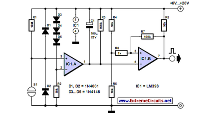
In practical implementation, the circuit should be housed in a durable enclosure to protect against environmental factors such as moisture and vibration, which are common in automotive applications. Proper insulation and strain relief should be considered for all connections to maintain circuit integrity over time. Additionally, the selection of high-quality components, such as the relay and reed switch, will contribute to the longevity and reliability of the system. Testing under various conditions, including different trailer loads and environmental scenarios, is essential to validate the design before deployment. This ensures that the system operates as intended, providing safety and compliance with applicable regulations.In most countries it is now mandatory or at least recommended to have a rear fog light on a trailer with the additional requirement that, when the trailer is coupled to the car, the rear fog light of the towing car has to be off. The circuit shown here is eminently suitable for this application. The circuit is placed near the rear fog light of the car. The 12-V connection to the lamp has to be interrupted and is instead connected to relay contacts 30 and 87A (K1, K3). When the rear fog light is turned on it will continue to operate normally. If a trailer with fog light is now connected to the trailer connector (7- or 13-way, K2), a current will flow through L1.
L1 is a coil with about 8 turns, wound around reed contact S1. S1 will close because of the current through L1, which in turn energizes relay Re1 and the rear fog light of the car is switched off. The fog light of the trailer is on, obviously. The size of L1 depends on reed contact S1. The fog lamp is 21 W, so at 12 V there is a current of 1. 75 A. L1 is sized for a current between 1. 0 and 1. 5 A, so that it is certain that the contact closes. The wire size has to be about 0. 8 mm. The relay Re1 is an automotive relay that is capable of switching the lamp current. The voltage drop across L1 is negligible. 🔗 External reference
Related Circuits
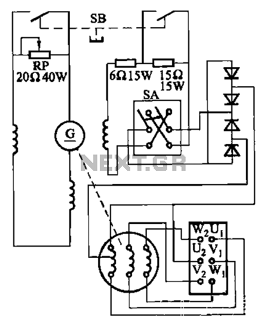
The AX3-300-2 DC arc welding machine circuit is part of the AX, AX1, AX3, and AR series of rotary DC arc welding machines. These machines share a similar structural design, featuring a three-integral unit configuration that combines an inverter...
A circuit that will find enough applications. Basically, the designing became in order to exist delay in quench one or more lamps in a stairwell or in any other space exists this need. It can become use for the...
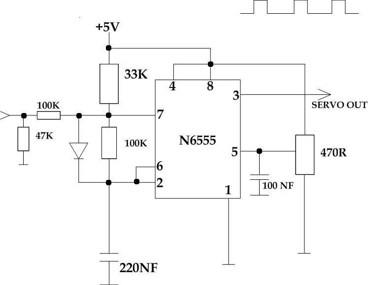
This circuit takes a standard 0-10V control voltage (for example, from an analog light control desk) and outputs a standard 1-2 ms control pulse for RC servo motors. The components used in this circuit include: - 2 x 100...
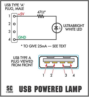
The device is referred to as the Itsy Bitsy USB Lamp. This concept is remarkably straightforward, raising the question of why it had not been conceived earlier. Originating as a student project at Massey University in Wellington, New Zealand,...
Mechanical contacts have the disadvantage that they wear out. That is why it is practical to use an electronic touch switch in some situations. The electronic touch switch serves as an effective alternative to mechanical contacts, addressing the issue of...
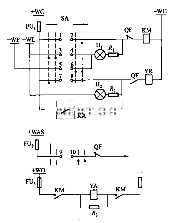
Factories and enterprises operating at voltages of 10 kV and below commonly utilize the CD10 (formerly CD2) type electromagnetic actuator as a circuit breaker. This mechanism features a mechanical anti-jump device. The control signal circuit for the CD10 actuator...