
Frequency/Tone Decoder with TC9400 FVC

The frequency-to-voltage converter (FVC) serves as an essential component in various electronic applications, particularly in tone or frequency decoding circuits. This type of circuit is designed to accurately detect and convert frequency signals into corresponding voltage levels, facilitating the identification of specific frequency bands of oscillation.
In a typical FVC circuit, an incoming oscillating signal is fed into the converter, where it undergoes processing to determine its frequency. The core component of the FVC is often an operational amplifier configured in a specific manner to achieve the desired frequency-to-voltage conversion. The circuit may also include resistors and capacitors that define the time constants and gain of the system, ensuring that the output voltage is proportional to the input frequency.
For tone decoding applications, the output voltage can then be used to trigger further actions, such as activating a relay, lighting an indicator, or interfacing with a microcontroller for digital processing. This makes the FVC circuit incredibly useful in communication systems, audio processing, and various automated control applications where precise frequency detection is crucial.
Moreover, the design of the frequency-to-voltage converter can be tailored to accommodate different frequency ranges and sensitivities, allowing for versatility in various electronic systems. By adjusting component values, engineers can optimize the circuit for specific applications, ensuring reliable performance across a range of conditions. Overall, the FVC plays a pivotal role in enhancing the functionality of electronic devices that rely on frequency analysis for operation.Another application of FVC (frequency-to-voltage converter) is tone/frequency decoder. This circuit is used to determine the frequency band of an oscillation. 🔗 External reference
Related Circuits
This circuit is designed to trigger on a 1 kHz tone. To change this frequency, refer to the table below, then change the resistor and capacitor values accordingly. More: all resistors are 5 or 10 percent tolerance, 1/4-watt; all...
A block diagram of the stereo TV decoder is presented. It illustrates the overall relationships between the separate sections of the circuit. The decoder section revolves around IC1, a standard 4.5-MHz audio demodulator. The output of IC1 is routed...
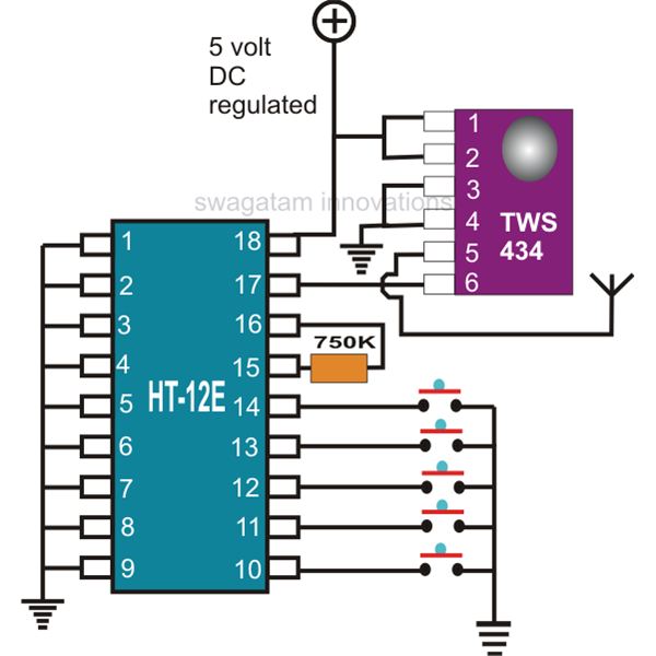
This document explains two RF 433kHz remote control chips specifically designed for remote control applications. The IC TWS-434, along with its encoder chip HT-12E from Holtek, forms a high-quality transmitter circuit, while the chip RWS-434, paired with the decoder...
To simplify the driver circuit, a multiplexer circuit can be utilized as a solution. With this multiplexed BCD decoder, only one BCD is required. A multiplexer (MUX) is an essential component in digital circuits, allowing multiple input signals to be...
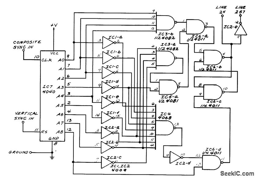
This circuit generates outputs on TV lines 24 and 257. It was utilized for a decoder circuit and employs a CMOS counter along with gate logic. Only one pin is designated for the output line indicator. The circuit described serves...
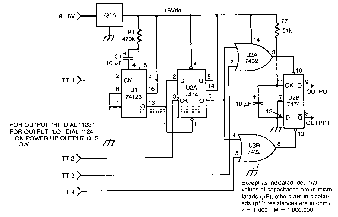
The circuit takes active low inputs from a Touch Tone decoder and reacts to a proper sequence of digits. The proper sequence is determined by which Touch Tone digits the user connects to the sequence decoder inputs TT1, TT2,...