
Fuel-cell battery tester

The circuit operates by utilizing a dynamic load configuration that allows for precise control over the current drawn from the fuel cell or battery under test. The TMOS Power FET (Q2) acts as the primary switching element, providing efficient operation at the required current levels. When switch SI is set to position 1, the emitter follower configuration formed by Q1 and R1 establishes a stable current reference. This configuration is crucial for maintaining the desired load current without manual intervention.
In position 2, the circuit can accept an external voltage signal to modulate the load current, providing flexibility for various testing scenarios. The operational amplifier U1 plays a critical role in regulating the load current. It receives feedback from the voltage drop across R15, which is directly proportional to the current flowing through the load. The feedback loop ensures that any variations in load current are corrected promptly, maintaining a constant current output to the fuel cell or battery.
The feedback mechanism is designed such that any increase or decrease in the voltage across R15 results in a corresponding adjustment in the output of U1. This maintains the load current at a constant value, which is essential for accurate testing of the device under evaluation. The adjustment potentiometer R13 allows for calibration of the feedback sensitivity, enabling the user to fine-tune the relationship between the voltage and current in the system.
The VOUT point serves as a monitoring output, providing a means to observe the performance of the circuit during operation. This allows for real-time assessment of the load conditions and the overall health of the fuel cell or battery being tested. The design is optimized for high current applications, making it suitable for rigorous testing environments where reliable performance and accurate measurements are paramount.This circuit was designed for testing fuel cells, but it could also be used for testing batteries under a constant current load. It provides a dynamic, constant current load, eliminating the need to manually adjust the load to maintain a constant load.
For fuel cell application, the load must be able to absorb 20-40 A, and since a single cell develops only 0.5 to 1.0 V, bipolar power devices (such as a Darlington) are impractical. Therefore, this dynamic load was designed with a TMOS Power FET (Q2). With switch SI in position 1, emitter follower Ql and Rl establish the current level for the load. In position 2, an external voltage can be applied to control the current level. Operational amplifier Ul drives TMOS device Ql, which sets the load current seen by the fuel cell or battery. The voltage drop across R15, which is related to the load current, is then applied to U2, whose output is fed back to Ul.
Thus, if the voltage across R15 would tend to change, feedback to the minus input of Ul causes that voltage (and the load current) to remain constant. Adjustment of R13 controls the volts/amp of feedback. The V0UT point is used to monitor the system.
Related Circuits
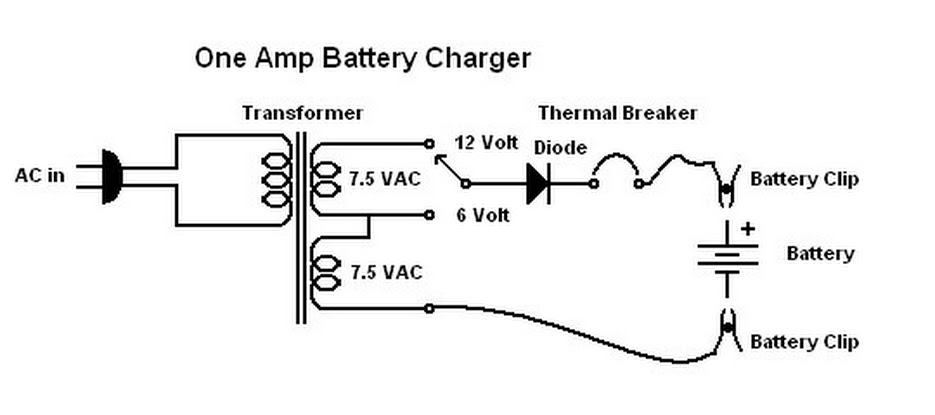
When this battery charger was purchased in 1970, it was not anticipated that it would still be relevant today. At that time, the owner had an old car with a weak battery that struggled to start in cold weather,...
This is a simple servo tester which will comprehensively test the capabilities of almost any modern servo. It has two pushbuttons, CENTRE and SWEEP and a potentiometer which works as follows: - CENTRE Does exactly that, centers the servo,...
This is a very simple circuit that can be used to test whether a pot is dry or not. When the two probes are inserted in wet soil, then the resistance between the sensors are low. The base of...
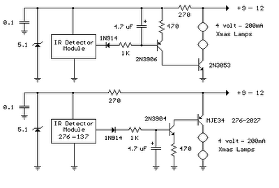
The infrared detector module (GP1U52X) (Radio Shack 276-137) generates a 5-volt TTL pulse train that corresponds to the digital code from a remote control button. In the circuit diagram, the module's output is normally low, producing a positive pulse...
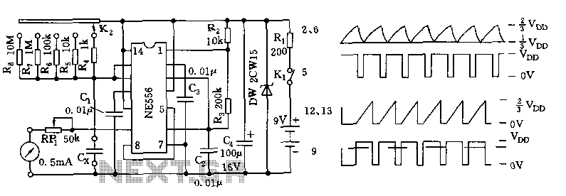
The tester comprises a dual time base circuit using a 556 timer and various RC components. The right side of the circuit features the 556 timer (556 1/2) along with resistors R2, R3, capacitors C2, C3, and additional components...
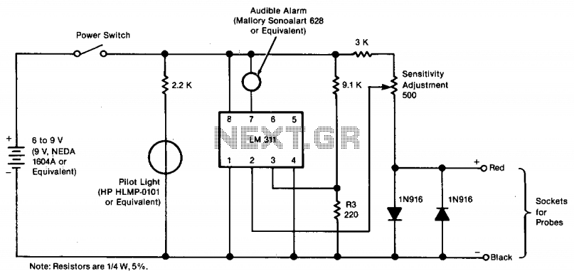
The tester provides an audible indication, eliminating the need for the user to directly observe a meter reading. Additionally, the current and voltage output of the tester are strictly limited, with a maximum of 0.6 volts DC and 3...