
Fully Functional Television Oscilloscope

To transform a television set into an audio visualizer, a detailed understanding of both the television's hardware and the audio signal processing is required. The primary objective is to utilize the television's display capabilities to create visual representations of audio signals.
The core components of this modification include an audio input source, a signal processing unit, and the television itself. The audio input can be derived from various sources such as a microphone, audio interface, or directly from a media player. The signal processing unit is essential for analyzing the audio signal and converting it into a visual format. This can be achieved using an Arduino or Raspberry Pi equipped with appropriate audio processing libraries.
The connection between the audio source and the processing unit can be established using standard audio cables. The output from the processing unit can be interfaced with the television through HDMI or composite video connections, depending on the television's input capabilities.
The processing unit will analyze the audio signal to extract features such as frequency amplitude and beat detection. This data will then be used to generate visual patterns or animations on the television screen. Various algorithms can be employed to create different visual effects, such as waveform displays, spectrograms, or beat-driven animations, enhancing the overall audio-visual experience.
Power supply considerations are also crucial, as both the processing unit and the television require adequate power. A dedicated power supply may be necessary to ensure stable operation without interference.
Overall, modifying a television set into an audio visualizer involves a combination of hardware interfacing, signal processing, and software programming, resulting in a unique and engaging audiovisual display.There are a few Instructables and otherwise internet based instructions on how to modify a television set into an audio visualizer or other simple.. 🔗 External reference
Related Circuits
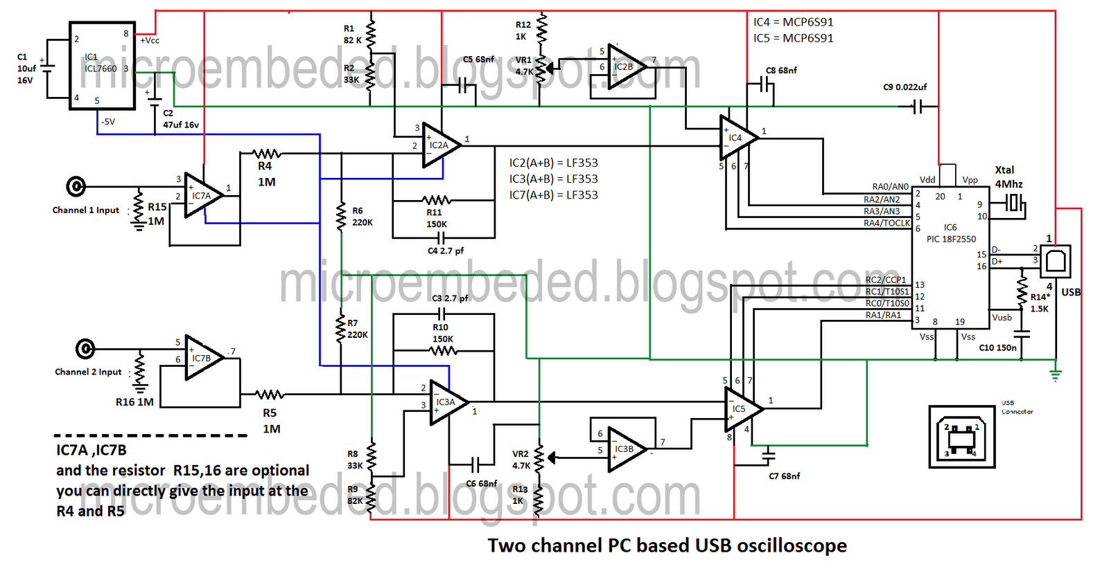
Portable PCs are now common, and a USB connection is a more effective solution. This document presents an oscilloscope that utilizes the USB port of a PC, operating at frequencies up to 10 kHz with an input voltage range...
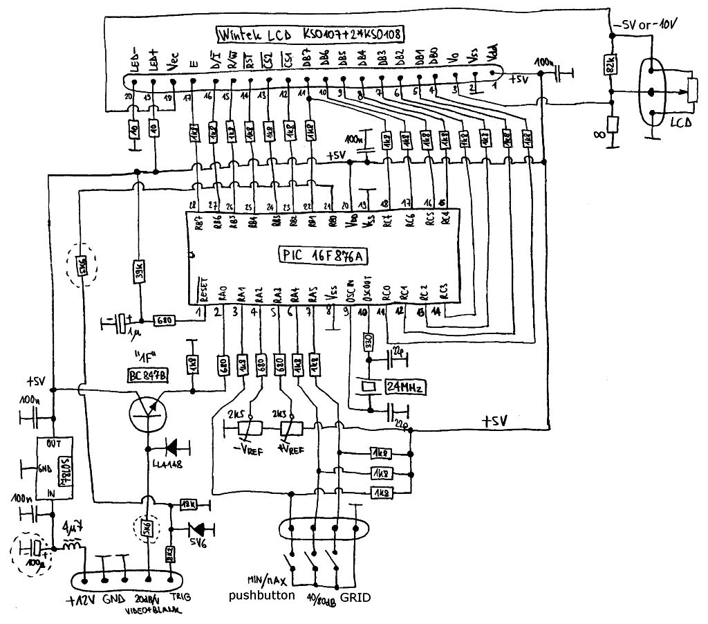
Spectrum-analyzer project 2007 update. Since the development of the wide-band VCO almost 10 years ago, the entire spectrum-analyzer project has progressed significantly. The spectrum analyzer project initiated in 2007 focuses on the development and enhancement of a wide-band Voltage Controlled...
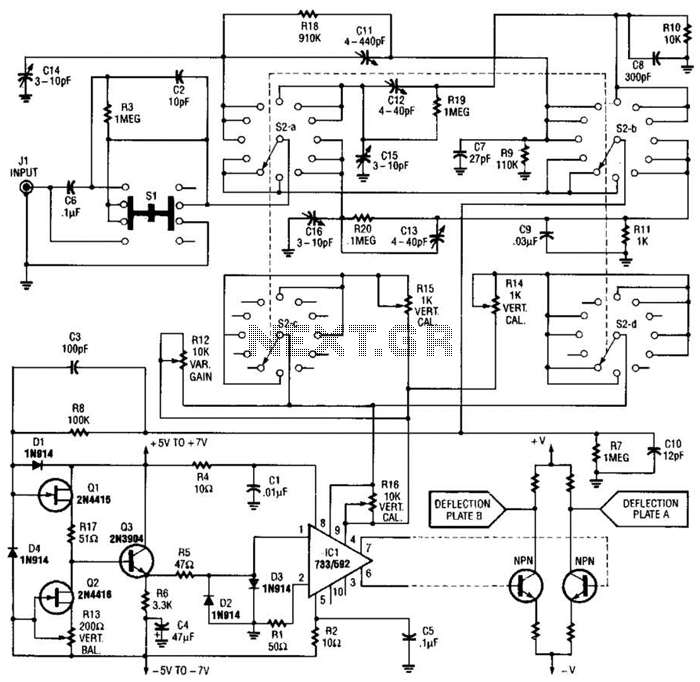
An oscilloscope front-end amplifier can be constructed using low-cost transistors and video amplifier integrated circuits (ICs). This preamplifier utilizes a FET input along with compensated attenuators, achieving an approximate bandwidth of 100 MHz, which is sufficient for most general-purpose...
The circuit below provides the horizontal drive voltage. The supply voltage on one end, +135 to +165, is made variable for the horizontal position control. The described circuit is designed to generate a horizontal drive voltage, which is essential in...
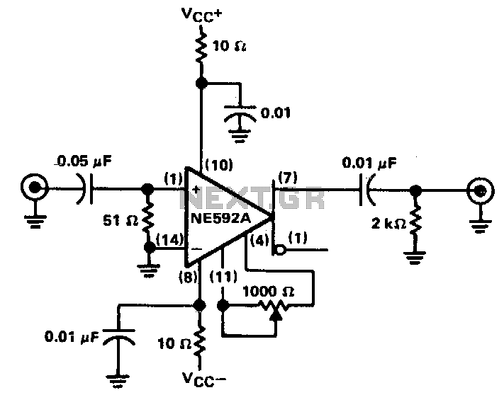
The circuit provides a voltage gain of 20 ±0.1 dB within a frequency range of 500 kHz to 50 MHz. The low-frequency response of the amplifier can be enhanced by increasing the value of the 0.05 µF capacitor connected...
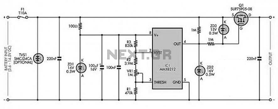
The circuit is designed to prevent over-voltage conditions in a battery during charging. It operates automatically to charge and recharge with a very low power consumption of less than 20mA, making it suitable for use with batteries rated between...