
GCA-60 silicon rectifier charging circuitry

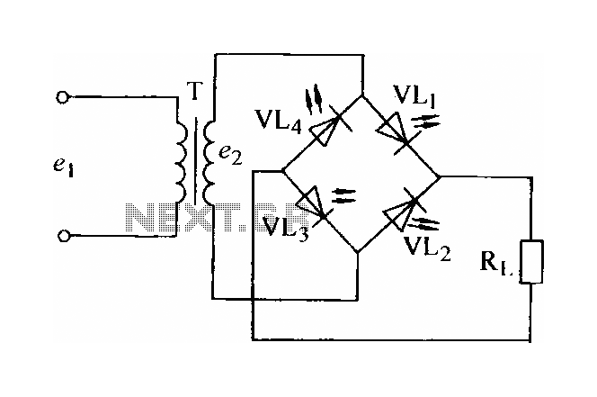
The three-phase bridge rectifier circuit is designed to convert three-phase alternating current (AC) into direct current (DC). This circuit configuration consists of six diodes arranged in a bridge formation, allowing for efficient rectification of the three-phase input. The diodes are typically rated for high voltage and current to accommodate the demands of industrial applications.
In this circuit, the three-phase AC supply is connected to the anodes of the diodes, while the cathodes are connected together to form the positive output terminal. The negative output terminal is connected to the common point of the diodes. During each half-cycle of the AC waveform, two diodes conduct, allowing current to flow to the load. This results in a pulsating DC output, which can then be smoothed using filtering techniques.
The output voltage from the rectifier is further regulated by a TY regulator. The TY regulator is a voltage regulation device that ensures a stable output voltage despite variations in the input voltage or load conditions. It typically employs feedback control mechanisms to adjust the output voltage to a desired level, thus improving the overall performance and reliability of the power supply system.
The specifications of the circuit can vary based on the application requirements, such as the voltage and current ratings, as well as the type of load being driven. Overall, this configuration is essential for converting three-phase power into a usable DC form for various electronic and industrial applications.It is a total of four kinds of specifications. Three-phase bridge rectifier circuit. The output voltage from the regulator TY regulation.
Related Circuits
In certain applications, the current from a non-rectified voltage power supply circuit is insufficient. A light-emitting diode (LED) rectifier circuit can be employed to address this issue, serving as a power indicator. It is important to ensure that the...
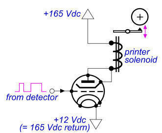
The 900 Hz tone is generated using an LC oscillator. The inductive component, "L," is provided by the inductance of the oscillator's output coupling transformer T1. This configuration is a variation of one of the two standard Hartley oscillator...
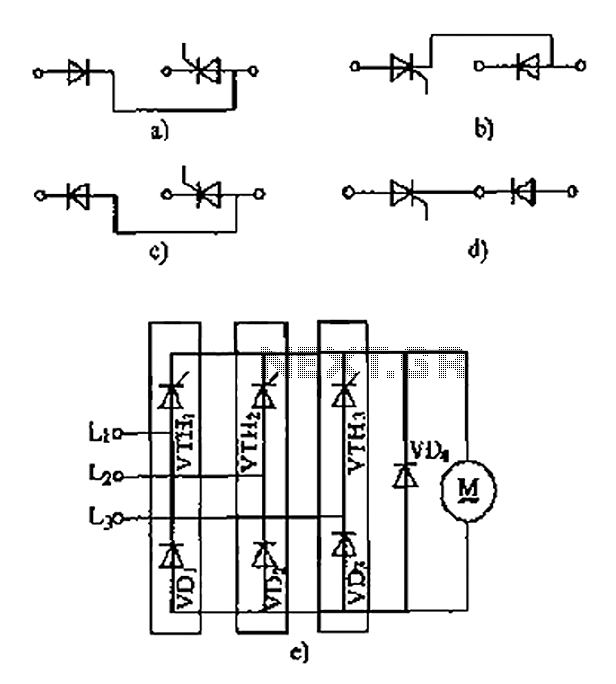
The thyristor linking arm rectifier module is a three-phase half-controlled bridge rectifier circuit. The thyristor-rectifier module linking arm consists of a thyristor and a rectifier diode connected in series or parallel, designed to fulfill specific requirements in power circuits....
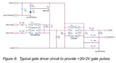
The silicon carbide (SiC) MOSFET offers notable advantages, including a straightforward drive circuit. It possesses unique characteristics that render it a superior switching device in comparison to traditional options. The silicon carbide MOSFET is a type of field-effect transistor that...

A high voltage battery pack will be utilized in both the eCRX and the electric race bike. A high voltage battery pack is a critical component in electric vehicles, providing the necessary energy storage to power electric motors effectively. In...
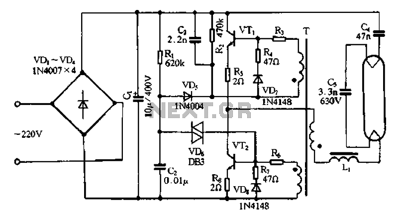
Bridge rectifier circuit in the electronic ballast application circuit The bridge rectifier circuit is a crucial component in electronic ballast applications, primarily utilized for converting alternating current (AC) to direct current (DC). This conversion is essential for powering various electronic...