
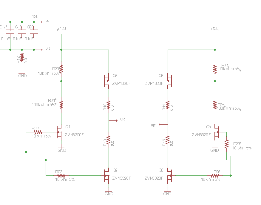
H-Bridge

This circuit drives small DC motors up to about 100 watts or 5 amps or 40 volts, whichever comes first. Using bigger parts could make it more powerful. Using a real H-bridge IC makes sense for this size of motor, but hobbyists love to do it themselves, and I thought it was about time to show a tested H-bridge motor driver that didn't use exotic parts. More: Operation is simple. Motor power is required, 6 to 40 volts DC. There are two logic level compatible inputs, A and B, and two outputs, A and B. If input A is brought high, output A goes high and output B goes low. The motor goes in one direction. If input
The H-Bridge circuit is a pivotal component in controlling the direction and speed of small DC motors, typically employed in robotics and automation applications. The design consists of four switches (transistors or MOSFETs), arranged in an H configuration. This configuration allows for the control of the motor's polarity, enabling it to rotate in either direction depending on the input signals.
For a standard implementation, the circuit operates with a DC supply voltage ranging from 6 to 40 volts, accommodating a variety of motor specifications. The four switches are labeled as S1, S2, S3, and S4, where S1 and S2 are responsible for one direction of rotation, and S3 and S4 are responsible for the opposite direction. The control inputs, A and B, are connected to a microcontroller or other logic-level devices that can provide high or low signals.
When input A is activated (set to high), S1 and S4 are turned on, allowing current to flow through the motor in one direction. Conversely, when input B is activated (set to high), S2 and S3 are turned on, reversing the current flow and thus the motor's rotation direction. This simple logic allows for straightforward control of the motor's operation without the need for complex circuitry.
To enhance the performance and reliability of the H-Bridge, it is advisable to include flyback diodes across each switch. These diodes protect the circuit from voltage spikes generated when the motor is switched off, which can occur due to the inductive nature of the motor winding. Additionally, implementing PWM (Pulse Width Modulation) on the inputs can facilitate speed control, allowing for variable motor speeds by adjusting the duty cycle of the control signals.
Proper heat dissipation measures should also be considered, especially when handling higher currents. Heat sinks or active cooling may be necessary to prevent overheating of the transistors or MOSFETs, ensuring longevity and consistent performance of the H-Bridge motor driver.
Overall, the H-Bridge circuit is a versatile and essential solution for controlling DC motors in various applications, providing both directional control and speed modulation capabilities.H-Bridge This circuit drives small DC motors up to about 100 watts or 5 amps or 40 volts, whichever comes first. Using bigger parts could make it more powerful. Using a real H-bridge IC makes sense for this size of motor, but hobbyists love to do it themselves, and I thought it was about time to show a tested H-bridge motor driver that didn`t use exotic parts.
Operation is simple. Motor power is required, 6 to 40 volts DC. There are two logic level compatible inputs, A and B, and two outputs, A and B. If input A is brought high, output A goes high and output B goes low. The motor goes in one direction. If input 🔗 External reference
Related Circuits
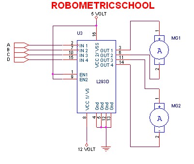
The electronic schematic of a DC motor driver using the L293D, as illustrated in Figure 2, enables the control of two DC motors continuously. It allows for one motor to rotate clockwise while the other rotates counterclockwise. Additionally, all...
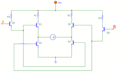
The transistors Q1, Q2, Q3, and Q4 form a bridge circuit. These are typically power transistors designed to handle high current. Transistors Q5 and Q6 drive the bridge. When input A is set high and input B is set...
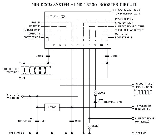
These circuits could be used as the basis for Model Railroad DCC Boosters or PWM motor controllers. The first schematic is for a basic 3 Amp - DCC Booster using the LMD 18200 CMOS, H-Bridge. Included in the design...
You have 4 transistors, wired as ON OFF switches. Two signal lines allow you to run the motor in one direction, when reversed, the motor runs in the other direction. It's very straightforward to use and build, but be...
Following the publication of a previous post, some unusual issues were encountered, which required several days to clarify. The main focus was on building a simple Class D amplifier designed to provide an EL panel with a +/- 120V...

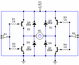
The 10A H-Bridge Motor Controller circuit appears straightforward, but several critical aspects should not be overlooked. The primary components utilized in the circuit include the TIP147, TIP142, and 2N2222 transistors. The power supply circuit operates at +12V, which is...