
Driving Relay with 555 IC

The driving relay circuit based on the 555 IC operates in a monostable or astable mode, depending on the configuration. The primary function of this circuit is to control a relay, which can switch larger loads than the IC can handle directly. The 555 IC is favored for its reliability and versatility in timing and switching applications.
In this circuit, the relay's coil is connected to the output pin of the 555 IC. When the IC outputs a high signal, the relay is energized, closing its contacts and allowing current to flow through the load. The inductive feedback mechanism is crucial in this design, as it prevents the 555 IC from hanging or becoming unresponsive due to the back EMF generated when the relay coil is de-energized. A flyback diode is typically placed in parallel with the relay coil to provide a path for the inductive kickback, thus protecting the 555 IC from voltage spikes.
The circuit may include additional components such as resistors and capacitors to set the timing characteristics of the 555 IC, determining how long the relay remains energized. Proper selection of these components is essential for achieving the desired operational behavior. The input to the 555 IC can be triggered by various means, such as a push button or another electronic signal, allowing for flexible application in different scenarios.
Overall, this driving relay circuit is an effective solution for controlling higher power loads while ensuring the reliable operation of the 555 IC through inductive feedback protection.This is a Driving Relay circuit using 555 IC. The circuit is used to drive a relay to avoid 555 hangs up, it uses an inductive feedback. The coil is prevented.. 🔗 External reference
Related Circuits
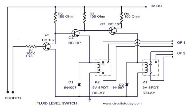
A simple liquid level switch circuit with diagram and schematic. This can also be used as a water level switch, fluid level switch, float level switch, and tank level switch. The liquid level switch circuit is designed to detect the...
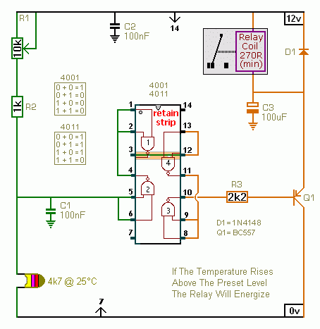
A CMOS 4001 or a CMOS 4011 can be utilized in this circuit, as both contain four two-input gates. The inputs of each gate are connected together, allowing them to function as simple inverters. This means that when both...
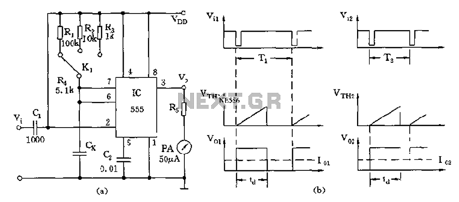
The circuit utilizes a 555 timer along with timing resistors R1 to R3 and a measured capacitance Cx to create a capacitance meter. The principle of capacitance measurement in a one-shot circuit is based on the relationship between the...
This 555 timer circuit below toggles a relay when a button is pressed. Pins 2 and 6, the threshold and trigger inputs, are held at 1/2 the supply voltage by the two 10K resistors. When the output is high,...
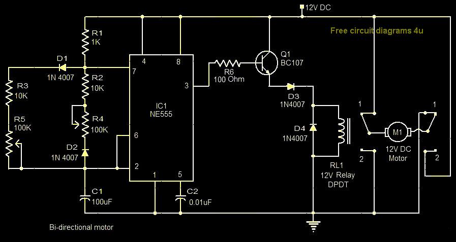
This circuit illustrates a bi-directional motor control circuit utilizing the NE555 integrated circuit (IC). Features include a 12V DC power supply, with the IC employed to control relay RL1. The bi-directional motor control circuit designed with the NE555 IC allows...
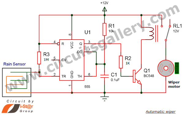
Have you seen Audi, Lexus, or Ford rain-sensing wipers and wondered how they operate in these vehicles? They are controlled by sensors located at the center of the windscreen, which detect raindrops and activate the wiper motor. The functioning...