
IR On/Off Switch Using Microcontroller

To implement a remote control system for switching electrical devices, a typical schematic would include several key components. The system generally consists of a remote control transmitter and a receiver module that interfaces with the target device.
The remote control unit typically operates using infrared (IR) or radio frequency (RF) signals. In the case of an IR remote, it emits modulated light signals that are detected by an IR receiver module connected to the device to be controlled. For RF systems, the transmitter sends radio waves that are captured by an RF receiver.
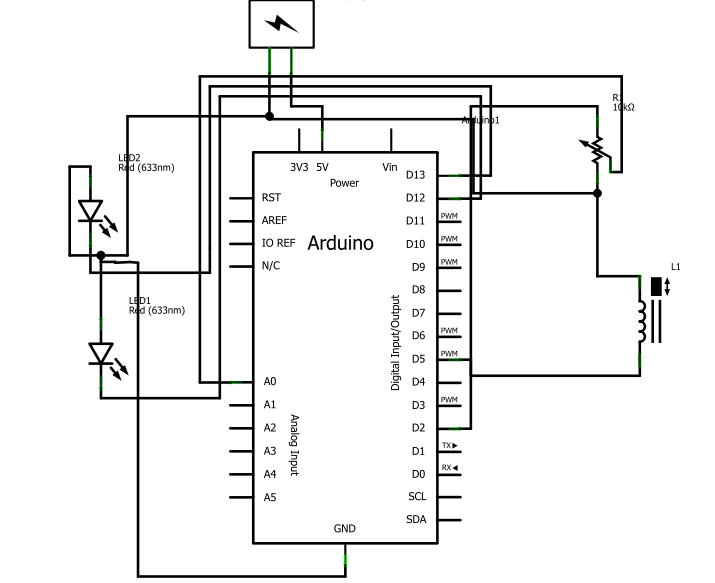
The receiver module will often include a microcontroller, which processes the incoming signals. The microcontroller is programmed to recognize specific command codes sent from the remote control. When a command is received, the microcontroller activates a relay or a solid-state switch that controls the power to the electrical device.
In addition to the basic components, the circuit may also include power supply elements, such as voltage regulators to ensure stable operation of the microcontroller and receiver. Protection components like diodes may be included to safeguard against back EMF when controlling inductive loads.
To enhance the system, additional features such as feedback mechanisms (e.g., LEDs indicating the status of the device) and user interface elements (like buttons or switches on the transmitter) can be integrated. This allows for more intuitive control and real-time feedback on the operation of the device.
Overall, the design of a remote control system for electrical devices involves careful selection of components, programming of control logic, and consideration of user interaction to create an efficient and user-friendly solution.Turn ON or OFF electrical devices using remote control is not a new idea and you can find so many different devices doing that very well. For realization.. 🔗 External reference
Related Circuits
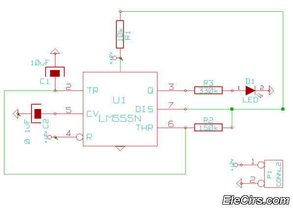
This is a very simple 555 timer circuit that serves as a straightforward theft deterrent, which may be just as effective. The idea is to have a flashing red LED indicate that your car is protected. This device can...
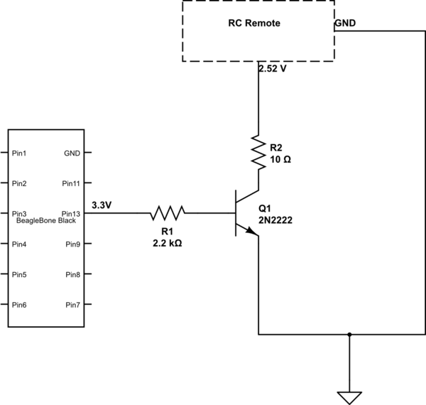
The remote control of an RC car was modified by extending wires from the backward, forward, left, and right switches. Grounding any of these wires completes the circuit and sends a signal to the car. The intention is to...
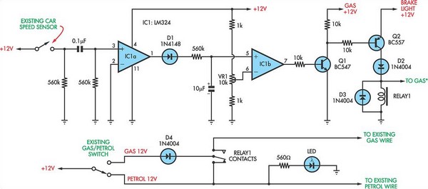
The following circuit illustrates a petrol gas switch sensor circuit diagram designed for a Pajero vehicle. It features a simple configuration utilizing the LM334 integrated circuit and operates automatically. The petrol gas switch sensor circuit is designed to monitor and...
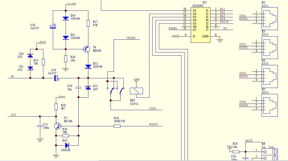
Create a simple telephone-based intercom system in a new house. Shouting between rooms is not effective, and using an instant messaging client or FaceTime lacks the immediacy of a voice call. A collection of old wired telephones is available...
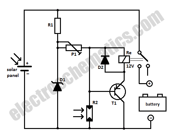
When charging a battery during the day using a solar panel, there is a risk of the battery partially discharging through the panel after sunset. This solar panel power switch circuit eliminates the need for a diode by utilizing...
After several days of considering electronic fuel injection for a moped, a decision has been made to proceed with the project. The required parts have been identified, and the remaining task involves programming. The implementation of electronic fuel injection (EFI)...