
Headlight delay unit

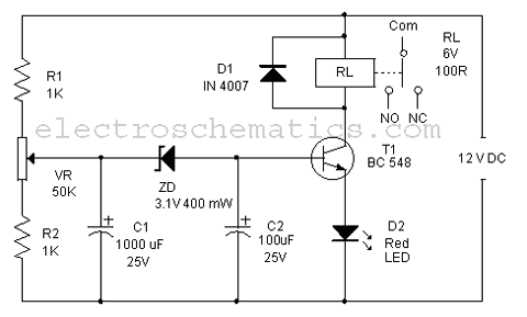
This circuit employs a simple timer mechanism utilizing a relay, transistors, and a capacitor to manage the operation of the car's headlights post-exit. The primary components include a relay for controlling the high-current headlights, and two transistors (Q1 and Q2) that function as electronic switches.
When the driver exits the vehicle and presses the switch SQ1, it triggers Q2, allowing current to flow through the relay coil. This energizes the relay, which closes its contacts and connects the car's headlights to the power supply, thereby illuminating the area. The use of a relay is crucial here, as it can handle the higher current required by the headlights without putting excessive load on the transistors.
Capacitor C1 plays a pivotal role in the timing aspect of the circuit. Initially, when SQ1 is pressed, C1 begins to charge through the variable resistor VR1, which allows for adjustment of the delay duration. The charging time of C1 determines how long the headlights remain on after the relay is activated. Once C1 reaches a certain voltage threshold, it activates Q1. This, in turn, turns off Q2, de-energizing the relay and opening its contacts, thus cutting power to the headlights.
The design allows for a customizable delay through the adjustment of VR1, making it adaptable to various user preferences. The circuit is efficient and reliable, providing a practical solution for enhancing safety and convenience when exiting a vehicle at night. Proper consideration should be given to the ratings of the components, particularly the relay and transistors, to ensure they can handle the expected load and operate within safe limits.This circuit will operate a car"s headlights for a predetermined time to light up the driveway or path after the driver has left the car. SQl is pushed and Q2 is turned on closing the relay and turning on the car"s headlights. Cl begins to charge through VR1 until Q1 turns on, turning Q2 off The relay will then open switching off both the lights and the unit. The delay is governed by the time taken for the capacitor to charge, which is about one minute.
Related Circuits

This is a simple touch switch circuit where the 555 timer is configured as a one-shot multivibrator triggered by touching the touch terminal. In monostable mode, the timer generates a fixed pulse of approximately 4 seconds whenever the trigger...
A very regular configuration of the 555 astable timer to work as a timer to trigger an alarm or any other equipment connected to pin 3. R resistor should be replaced with a potentiometer that will change the time...
The 555 integrated circuit is utilized in a delay circuit configuration, functioning as a one-shot timer. The delay time can be adjusted using resistor R3 and capacitor C3. Typical values for R3 range from 1 kΩ to 10 MΩ,...
Time delays ranging from 0 milliseconds to over three minutes can be achieved with this circuit without the need for tantalum or electrolytic capacitors. The timing interval begins when power is applied to the circuit. At the conclusion of...
Protect your LCD or Plasma TV with this small delay-on circuit. The SMPS-based power supply of these modern electronic devices is susceptible to voltage spikes. This delay-on circuit is designed to enhance the protection of LCD and Plasma TVs by...
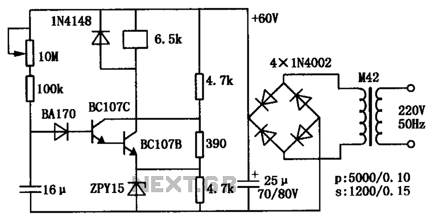
The circuit consists of a transistor relay delay pull mechanism. Initially, with a 16 µF capacitor at zero voltage, both transistors are off, and the relay remains inactive. As the 16 µF capacitor charges over time, the voltage increases...