
Headphone Limiter

To create a circuit that connects headphones to a metal detector while incorporating a variable potentiometer for volume control, a basic schematic can be designed. The circuit will consist of the following components: a potentiometer, two 1N914 diodes, and the headphone output.
1. **Potentiometer**: A variable resistor (potentiometer) is used to adjust the audio level. The value of the potentiometer can typically range from 10kΩ to 100kΩ, depending on the desired control range. This component will be connected in series with the headphone output to allow for volume adjustment.
2. **Diodes**: The use of two 1N914 diodes across each channel serves to limit the voltage that can cross over from the metal detector to the headphones. The diodes should be oriented in opposite directions to allow for effective clamping of the signal. When the voltage exceeds the forward voltage drop of the diodes (approximately 0.7V for silicon diodes), they will conduct and limit the voltage to the headphones, thereby protecting them from potential damage.
3. **Voltage Limiting Calculation**: To determine how much the diodes are limiting the voltage, one can use the following formula:
- V_limit = V_forward + (R_load / R_diode) * I_load
where V_limit is the maximum voltage across the headphones, V_forward is the forward voltage drop of the diodes (typically around 0.7V), R_load is the effective resistance of the headphones, R_diode is the dynamic resistance of the diodes when conducting, and I_load is the current through the headphones.
4. **Schematic Layout**: The schematic will show the potentiometer connected in series with the headphone output, with the two diodes placed in parallel across the output terminals of the potentiometer. The anode of one diode connects to the positive terminal of the headphones, while the cathode connects to the negative terminal, and vice versa for the second diode.
This design ensures that the user can adjust the volume of the audio signal while protecting the headphones from excessive voltage that could arise from the metal detector's output. Proper component selection and layout will enhance the performance and reliability of the circuit.I need one to put in between my headphones and my metal detector. I don`t need anything fancy, but would like to be able to use a pot and make it variable. I`m sure this can be done, I have looked and either don`t understand it, or it`s just not what I`m looking for. So if there is someplace where it is simply put and laid out could you point me in the right direction, or post a plan here please. Thanks for your time. Oh ok, I will give that a try, so say if I had two 1N914 across each channel it would limit however much of the voltage was trying to cross over, then If I used a different size that limit would change. I get that, and it`s easy, so one more question how to I figure out how much it is limiting when using the diodes, I`m sure that there is a formula someplace.
thanks guys. 🔗 External reference
Related Circuits
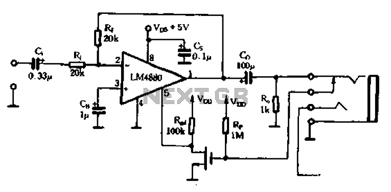
Enthusiasts understand that connecting headphones directly into the universal headphone jack to listen to VCD results in subpar sound quality. The audio performance when using a tape player is similarly affected. An amplifier is necessary, and the RC4558, which...
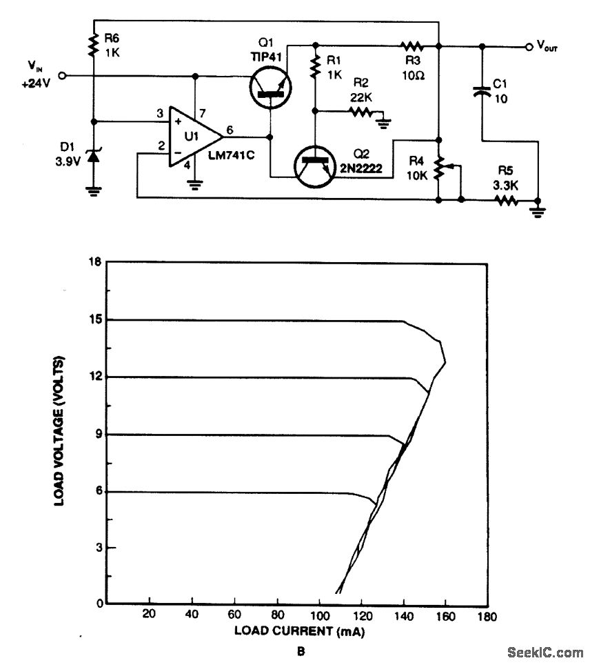
This regulator utilizes the voltage drop across resistor R3 to monitor current draw. When the current exceeds a certain threshold, Q2 is activated, which in turn disables Q1 and reduces the output voltage. Current limiting takes place when Q2...
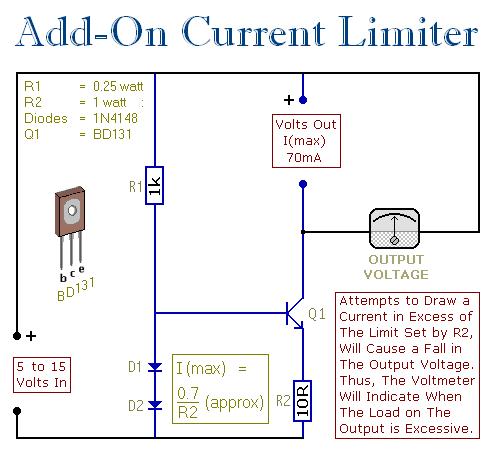
This circuit allows you to set a limit on the maximum output current available from your PSU. It's very useful when you power-up a project for the first time or carry out a soak-test. By setting an upper limit...
To determine the loudness of different headphones, one must calculate the power delivered to each headphone based on the source impedance. It is likely that the source impedance is closer to 32 ohms than to 250 ohms, suggesting that...
This design for a headphone amplifier arose after the purchase of commercial equipment with separate pre and power amplifiers without a headphone output. Its advantages are low output impedance to drive several pairs of phones, the active gain stage...
In addition to its primary function as a headphone amplifier, the circuit is suitable for various applications requiring a wide bandwidth low power amplifier. It is constructed using an operational amplifier (op-amp), with its output current enhanced by a...