
Hi-Fi Headphone Amplifier

The headphone amplifier circuit is designed to enhance audio signals from preamplifiers to drive headphones efficiently. Key features include a low output impedance, which is crucial for driving multiple pairs of headphones without significant degradation in audio quality. The active gain stage employs a logarithmic response, ensuring that volume adjustments are perceived as smooth and natural, improving user experience.
The circuit incorporates a potentiometer that does not affect the logarithmic gain characteristics, allowing for consistent audio performance across different settings. This feature is particularly beneficial in maintaining excellent channel tracking, ensuring that both left and right audio channels are balanced regardless of volume level. Additionally, the design minimizes output noise as the gain is reduced, enhancing the overall sound clarity, especially at lower volumes.
For integration within a larger audio system, the headphone amplifier can be permanently connected between the preamplifier and power amplifier. This configuration allows it to serve as a dedicated headphone output without interfering with the main audio signal path. Alternatively, it can function as a standalone unit, providing flexibility for various audio setups.
The inclusion of an input relay is a notable design consideration. This relay is triggered by auxiliary contacts on the headphone sockets, allowing for automatic switching between headphone and speaker outputs. The relay is controlled by a transistor driver, which introduces a small delay to prevent popping sounds during switching, thereby protecting both the headphones and the amplifier.
Overall, the headphone amplifier circuit is engineered for high fidelity and versatility, making it an excellent addition to any audio system requiring headphone connectivity.This design for a headphone amplifier arose after the purchase of commercial equipment with separate pre and power amplifiers without a headphone output. Its advantages are ... * low output impedance to drive several pairs of phones * the active gain stage is, almost, perfectly logarithmic and ...
o is independent of the absolute value of the pot o has excellent channel tracking o the O/P noise reduces with gain reduction. The intention is to permanently insert the headphone amp between pre and power amps, although it can be used as a stand-alone item. The input relay is operated by auxiliary contacts on the headphone sockets through a transistor driver (with a small delay)
🔗 External reference
Related Circuits
A simple preamplifier circuit is often required, utilizing a few components for ease of construction. This circuit employs an operational amplifier, specifically the Motorola TCA5550, which features a dual amplifier configuration. It provides outputs for adjusting volume, balance, treble,...
This diagram originates from the Progressive Communications Receiver featured in most recent ARRL Handbooks. The amplifier is utilized wherever an intermediate frequency (IF) amplifier is necessary. W6BKY has published an article on Hamradio-online that details the construction of this...
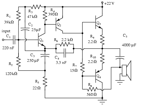
Note that Q3 and Q4 in the figure below are complementary, with Q3 being an NPN transistor and Q4 being a PNP transistor. This circuit is suitable for moderate power audio amplifiers. For a detailed explanation of this circuit,...
A 10 Watt audio amplifier circuit diagram is presented. This circuit serves as a general-purpose 10-W power audio amplifier, suitable for medium power applications or for use in modulation within AM transmitters. To achieve higher power levels, up to...

A simple instrumentation amplifier circuit diagram utilizing an operational amplifier (op-amp). The equation for gain, along with design, working principles, and construction details, are also provided. An instrumentation amplifier is a type of differential amplifier that has been designed to...
Utilize this FM antenna amplifier in locations where the reception of FM stations is poor. This circuit is specifically designed for this purpose. The FM antenna amplifier circuit is engineered to enhance signal strength for FM radio stations, particularly in...