
HiFI Headphone Amplifier

The CMoy headphone amplifier PCB design represents a compact and efficient solution for portable audio amplification. The integration of a bass-boost circuit enhances the listening experience by allowing users to tailor sound profiles to their preferences, particularly for low-frequency audio. The design's compatibility with various operational amplifiers provides flexibility in component selection, enabling users to customize performance characteristics based on specific audio requirements.
The implementation of a constant current charger for the 9V battery ensures that the amplifier remains powered during extended use, while the inclusion of blocking capacitors (C3+ and C3-) protects the op-amp from potential power supply fluctuations. The design's careful consideration of component placement, particularly the vertical orientation of resistors and diodes, maximizes space efficiency within the confined dimensions of the Altoids tin.
The use of a Rail Splitter (V1) to establish a virtual ground is critical for the proper functioning of the op-amp circuit, as it allows for balanced operation in a single-supply configuration. The high-quality blocking capacitor (C1) with low ESR contributes to improved audio fidelity by minimizing signal distortion.
Overall, this PCB design not only meets functional requirements but also considers user experience through its compact form factor and customizable features, making it an excellent choice for audiophiles seeking portable amplification solutions.This is an article about my new PCB design for CMoy headphone amplifier. Main feature is that the new PCB fits exactly to the classic Altoids tin-can. This new CMoy incorporates moreover bass-boost circuit and constant current charger for 9V battery. P1 is the volume potentiometer with On/Off switch. C2 is coupling capacitor. R2 defines the input impedance of opamp. R3 and R4 define the gain of the amplifier (5x in this case). Rb and Cb form bass-boost circuit. These components increase the gain for low frequencies. For the low frequencies the gain is 14. By increasing the Rb resistors you can increase the gain for low frequencies and vice verse. You can decrease the cutting frequency by increasing the Cb capacitors. Bass-boost can be deactivated by shorting out Rb resistors. As a opamp I use OPA2132, but many others can be used as well like OPA2134, OPA2227, NE5532, . C3+ and C3- are blocking capacitors for power supply for opamp. R5 is optional, but to avoid some bouncing at the output the value should be around 22 ohms. V1 is a Rail Splitter which creates virtual ground. C1 is high quality blocking capacitor with low ESR. Resistor R1 limits the current through LED. The value should be modify according the type of LED. D2 limits the maximum voltage in the input to 12V. U2 together with resistor R0 create constant current source for charging the 9V battery. In my case the R0 has value 47 ohms and then the current is around 25mA. Cin is tantalum blocking capacitor for U2. D1 is Schottky diode for avoiding any damage when the voltage with opposite polarity is connected. I designed the PCB with two rounded corners. The PCB fits exactly to the Altoids tin (see pictures below). On the PCB are also nice pictures of input jack and headphones. The resistors and diodes must be assembled vertically to reduce occupied space. 🔗 External reference
Related Circuits
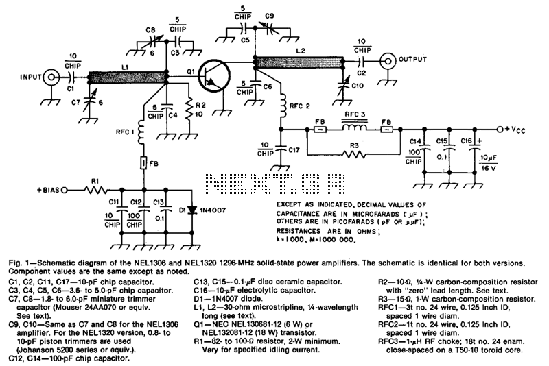
The design incorporates 30-ohm, 1/4 microstrip lines on the input and output. Capacitors C3, C4, C7, and C8, along with inductor L1, form a pi network that matches the low input impedance of the device to 50 ohms. Capacitors...
This is a circuit that ensures that you can connect two amplifiers together so you get more power. When called in bridge linking two amplifiers plus you can link the outputs of the amplifiers to the speaker. One of...
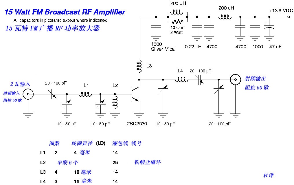
This FM broadcast RF amplifier is constructed using the 2SC2539, which is a silicon NPN epitaxial planar type transistor designed for RF power amplifiers in the VHF band. The FM broadcast RF amplifier utilizing the 2SC2539 transistor operates effectively within...
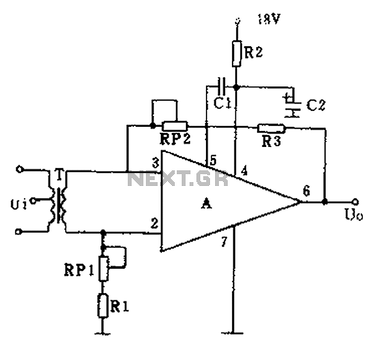
The operational amplifier A is utilized in an audio preamplifier circuit. Its advantages include compact size, low noise, low power consumption, and excellent consistency. The operational amplifier can achieve significant negative feedback while increasing output without distortion. The signal...
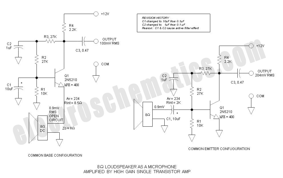
Single Transistor Amplifier Revisited Part 3, Common Base vs Common Emitter Configuration, Update One nagging question that I have long had is this: How do... The single transistor amplifier is a fundamental building block in electronic circuits, and its configurations—common...
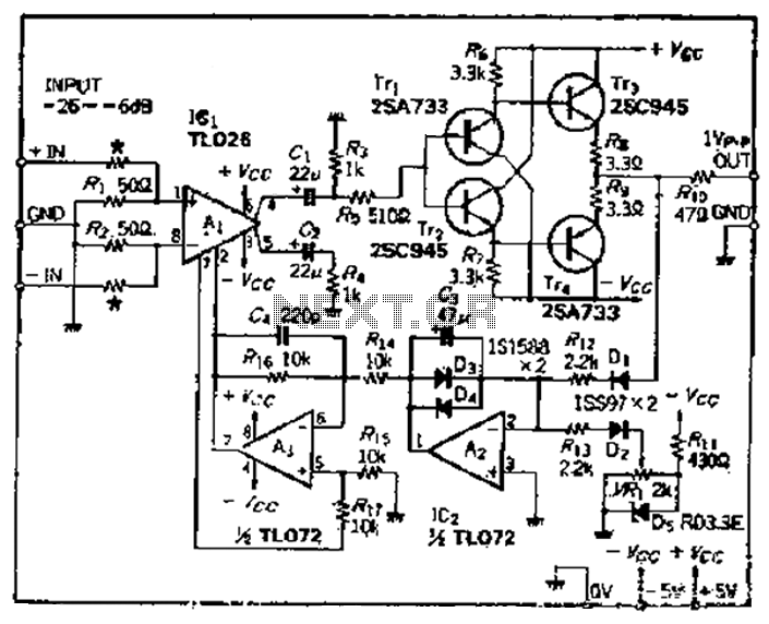
A car circuit is utilized for external voltage-controlled amplification in wideband amplifiers using the TL0216 IC. This design incorporates compression characteristics of 2dB. The input circuit consists of resistors that reduce the input level when it is between -26dB...