
Soldering Iron Control Circuit

The circuit employs the TL783 voltage regulator, which is designed to provide a stable output voltage while allowing for adjustable current control. This feature is essential for maintaining the desired temperature of the soldering iron. The TL783 can handle input voltages up to 125 V and output currents of up to 700 mA, making it a robust choice for this application.
To implement this circuit, several key components are required. The input voltage should be appropriately selected based on the power supply available, ensuring it remains within the operational limits of the TL783. The output voltage can be adjusted using a potentiometer connected to the adjust pin of the regulator, allowing for fine-tuning of the soldering iron's temperature.
Additional components may include capacitors for stability and filtering, as well as resistors to set the desired output voltage. It is critical to choose these components based on the specific characteristics of the soldering iron being used. For a 25 W soldering iron, the output current should be limited to approximately 1 A, which can be achieved by selecting appropriate resistor values in the feedback loop of the TL783.
Thermal management is also a crucial consideration in this circuit design. The TL783 may require a heatsink to dissipate heat generated during operation, especially when operating near its maximum current rating. Proper layout and thermal considerations will enhance the reliability and performance of the soldering iron temperature control circuit.
Overall, this current control circuit provides an effective means of regulating the temperature of a soldering iron, ensuring optimal performance for soldering applications. A current control to temperature regulate a soldering iron uses a high-voltage integrated regulator, TL783 (Ul). With the component values specified, the circuit should be used with a soldering iron of 25 W or less.
Related Circuits
Hello everyone, I am not well-versed in electronics, so I would appreciate it if someone could create a diagram for me. I would like to modify a circuit so that it can dial a number using speed dial and...
Xenon lamp, strobe light circuits, xenon strobe, photo flash, photoflash, schematics or diagrams, all free to use. The inspiration originated from a strobe circuit that was part of a school fire alarm. Xenon lamps are high-intensity discharge lamps that emit...
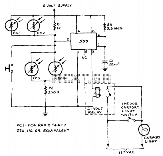
A 555 timer integrated circuit (IC) functions in one-shot mode, triggered by light exposure to photoresistors. These photoresistors typically exhibit a resistance in the range of several megohms, which decreases to several hundred ohms under light conditions, allowing current...
The core component of this DIY metal detector circuit is the CS209A. The metal detector is constructed with a single coil of 100 µH. The CS209A contains an oscillator that forms an LC circuit; the inductance of the coil...
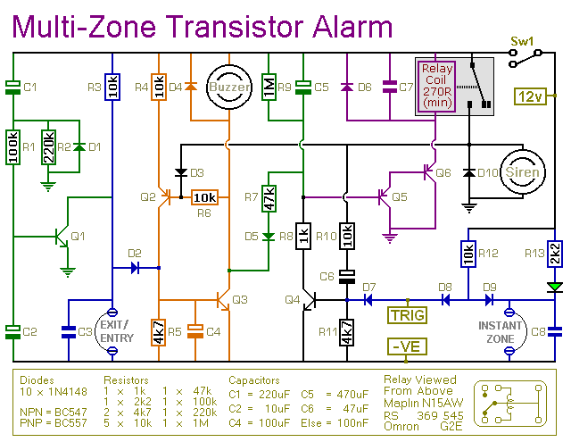
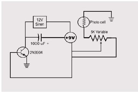
This transistor-based alarm features automatic exit and entry delays, along with a timed bell cut-off and system reset. In addition to the exit/entry zone, the basic alarm board includes one instant zone, which is sufficient for many applications. However,...
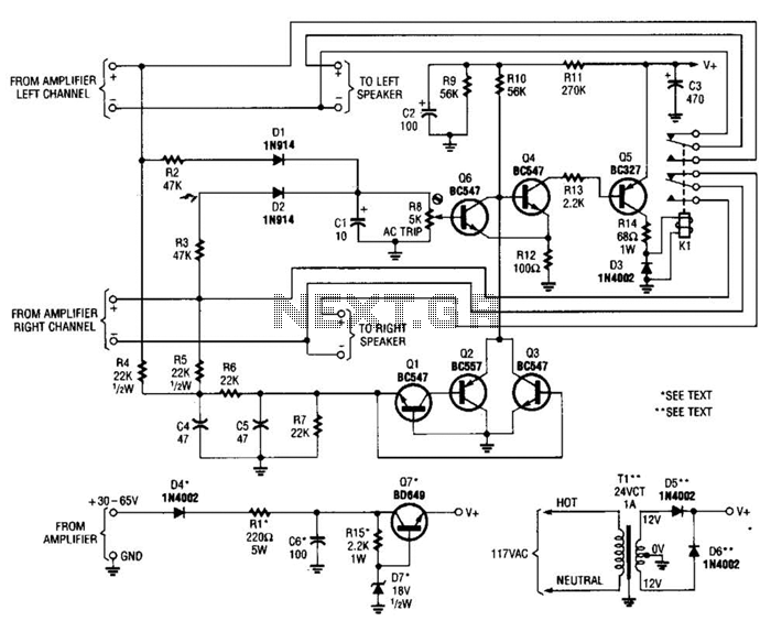
Most of the transistors in this speaker protector operate as switches. Normally, Q4, Q5, and K1 are activated, allowing the speakers to connect to the amplifier. However, if a significant DC voltage is detected at the amplifier output, either...