
HiFi stereo preamplifier with tone control

The preamplifier circuit described is designed for ease of assembly on a printed circuit board (PCB) and incorporates a unique tone defeat function, allowing for nuanced control over audio output. The tone controls do not completely disengage; instead, they are de-sensitized to provide a more subtle adjustment range. This flexibility allows users to switch between a standard tone control setting offering a ±10dB boost or cut, and a gentler setting with a ±3dB adjustment, ideal for minor tonal tweaks during regular listening sessions.
The compact design of the PCB is optimized for space efficiency, utilizing 16mm potentiometers. The volume potentiometer is strategically placed further apart from the other controls to accommodate a larger knob, reflecting its importance as the primary user interface in the preamp. The input stage of the circuit is configured to provide a gain of 2 (6dB) and functions as a buffer for the tone control section, ensuring minimal signal degradation.
The tone control employs a Baxandall configuration, enhanced by additional resistors (R117, R118, and R119) that facilitate easy reconfiguration. This design choice allows for greater flexibility compared to traditional tone control circuits, which often center around 1kHz and significantly affect midrange frequencies. The performance characteristics of the tone control are illustrated in accompanying figures, demonstrating minimal impact on midrange audio, a desirable feature for audiophiles seeking fidelity.
For optimal performance, the circuit is designed to operate with TL072 op-amps or equivalent, with a cautionary note against using lower-grade op-amps due to potential noise and frequency response limitations. The schematic includes a standard pinout for dual op-amps, emphasizing the importance of correct installation to prevent damage.
Construction is simplified when using the PCB, with comprehensive assembly instructions and a Bill of Materials provided. However, if the PCB is not utilized, careful attention to wiring and layout is necessary to avoid issues such as crosstalk and oscillation. Notably, resistor R119 plays a critical role in defining the tone control range, and adjustments to its value can significantly alter the circuit's response, allowing for customization based on user preference.
Overall, this preamp circuit is designed for versatility and ease of use, making it suitable for integration with power amplifiers in a complete audio system. The option to modify tone control characteristics and the straightforward assembly process contribute to its appeal among audio enthusiasts and engineers alike.The preamp featured is very straightforward to make on the PCB, and has an innovative tone defeat function. Rather than completely disable the tone controls, they are massively de-sensitised, and when "defeated" have a maximum range as shown in Fig.
3 (below). This can be increased if desired, so you can have two tone control settings, one with the normal 10dB boost and cut, and the other with a very subtle 3dB boost and cut - this will be enough (surprisingly) for very minor adjustments such as you might need for day-to-day listening. As you can see, the PCB is very compact. The volume pot is actually spaced a little further apart than the others to allow a larger knob, since this is the most commonly used control in any preamp. The use of 16mm pots makes for a small and neat layout, and makes it very easy to include the preamp with a power amp, making a complete integrated amplifier system.
he input stage is configured as shown with a gain of 2 times (6dB), and also acts as a buffer for the tone control circuit. The tone control is a basic Baxandall type, but the addition of R117, 118 and 119 provide flexibility and easy reconfiguration that is not available with the traditional arrangement.
The tone control (and overall) performance is shown in Figure 2 (10% steps of the pots), and it can be seen that the midrange is barely affected. This is in contrast to the majority of designs, where the controls are centred on 1kHz, and there is a very audible effect in the midrange frequencies.
For those who absolutely do not want to use tone controls, I suggest the DoZ preamp (Project 37) or Project 88 - both were designed with no tone controls and are more in the line of true minimalist designs. Note that although shown using TL072 opamps, OPA2134 or anything else that suits your purposes may be used instead.
I do not recommend using anything less than a TL072, even for the workshop or rumpus room, as there will be excessive noise and limited frequency response - this in turn limits the usefulness of the preamp. The standard pinout for a dual opamp is shown on the left. If the opamps are installed backwards, they will almost certainly fail, so be careful. The suggested TL072 opamps will be quite satisfactory for most work, but if you prefer to use ultra low noise or wide bandwidth devices, that choice is yours.
Remember that the supply earth (ground) must be connected! When powering up for the first time, use 100 ohm to 560 ohm "safety" resisors in series with each supply to limit the current if you have made a mistake in the wiring. If the PCB is used, construction is a snap. As usual, all construction notes, Bill of Materials and recommended layouts will be available shortly.
If you choose not to use the PCB, wiring is a little more challenging, since there are quite a few parts, and some wiring routing is reasonably critical if excessive crosstalk and oscillation is to be avoided. R119 is the tricky part in this circuit (which is unique, by the way - I have not seen this technique used before).
As shown it is 100k, and this limits the tone control range to a sensible +/-10dB. To obtain more boost and cut, R119 (and R219) may be omitted altogether. Conversely, reducing the value will give a smaller range, with about 6dB at 20Hz, and 7.5dB at 20kHz with 22k. Note that the Rev-A board is slightly different from the Rev - circuitry shown here. The differences are not great, but you do need the info in the secure site to see where the various parts are located.
🔗 External reference
Related Circuits
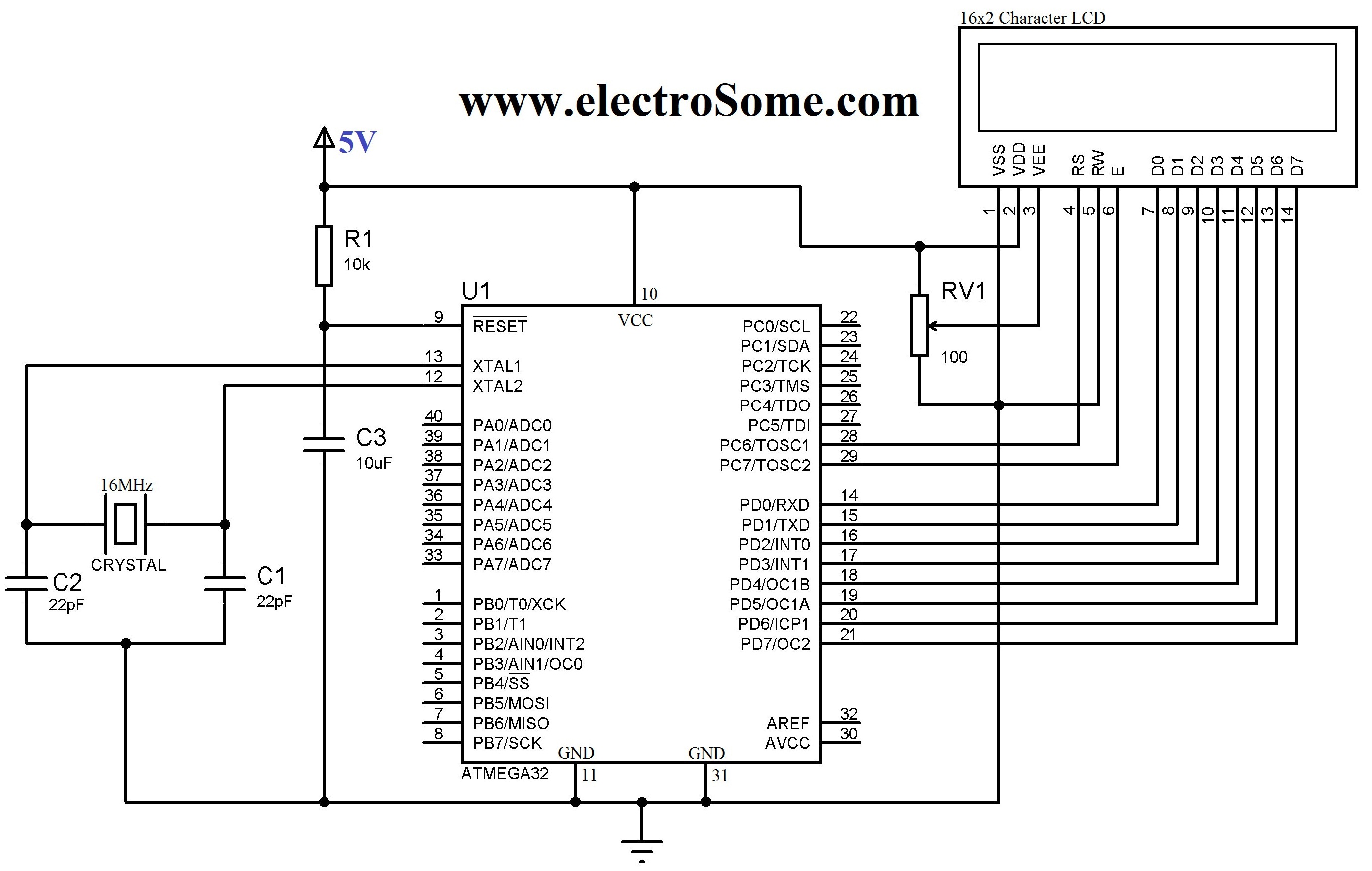
An LCD (Liquid Crystal Display) is a widely used electronic display found in devices such as calculators, laptops, tablets, and mobile phones. The 16G-2 character LCD module is a fundamental component frequently utilized by electronics enthusiasts and integrated into...
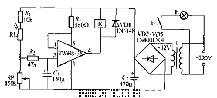
Automatic lights using a light sensor, the TWH87SL power switch integrated circuit consists of a first input terminal TWH8751 connected to the positive terminal of the power supply. The output pin state is determined by the strobe terminal, which...
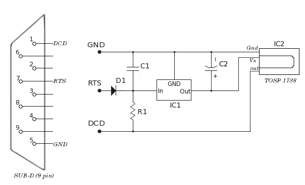
Envision a scenario where one is comfortably reading a favorite novel while enjoying music on a computer. Suddenly, the desire arises to skip the current song or pause the MP3 player. An infrared software solution is available that decodes...
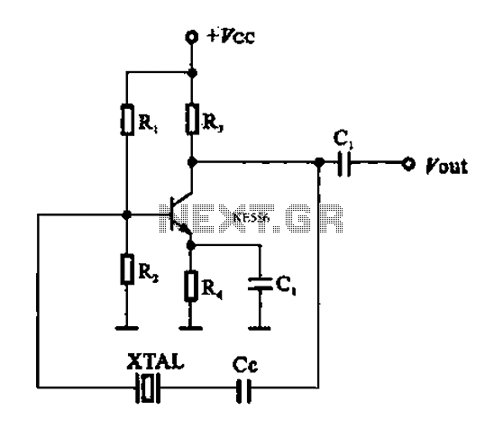
A series resonant circuit utilizing a crystal oscillator is illustrated. The crystal impedance reaches a minimum value at the series resonance frequency, resulting in a significant feedback amount. The crystal tuning capacitor (Cc) can slightly adjust the resonance frequency...
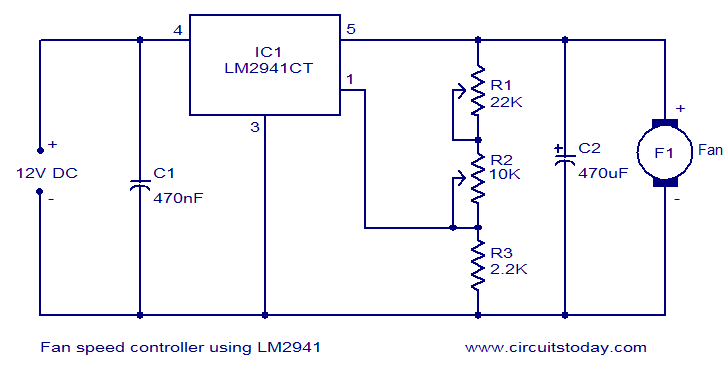
Numerous electronic circuits designed for fan speed control have been documented, and this one presents an alternative method. The circuit diagram illustrates a 12V DC fan speed controller utilizing the LM2941CT integrated circuit, which is a low dropout 1A...
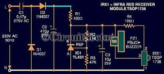
An infrared remote control tester circuit that can be constructed inexpensively. This IR tester is built around an infrared receiver module TSOP1738. The remote control's state can be observed through the sound of a buzzer. The circuit is highly...