
High-Current Battery Discharger

This circuit is designed to evaluate the capacity of 12V batteries, which may be in varying states of health. The schematic typically includes a battery holder, a load resistor, and a voltmeter or an ammeter to measure voltage and current, respectively.
To begin, a battery holder is utilized to securely connect the 12V battery being tested. The load resistor is selected based on the desired discharge rate, which should ideally match the typical load that the battery would experience in practical use. The resistor allows the battery to discharge at a controlled rate, providing accurate readings of its capacity.
The voltmeter is connected across the battery terminals to monitor the voltage drop as the battery discharges through the load resistor. An ammeter may also be included in the circuit to measure the current flowing through the load, which can help in calculating the total capacity in ampere-hours (Ah).
To perform the capacity test, the battery is connected to the circuit, and the load is applied. The voltage and current readings are recorded at regular intervals until the voltage drops to a predetermined cutoff level, typically around 10.5V for a 12V battery. This information can then be used to calculate the total capacity of the battery by integrating the current over time.
In summary, this simple circuit provides a practical method for assessing the capacity of 12V batteries, allowing users to determine their viability for various applications. Proper selection of components and careful monitoring of the discharge process are crucial for obtaining accurate capacity readings.If you have a motley collection of 12V batteries in varying states of health, this simple circuit will allow you to easily check their capacity. It s basi.. 🔗 External reference
Related Circuits
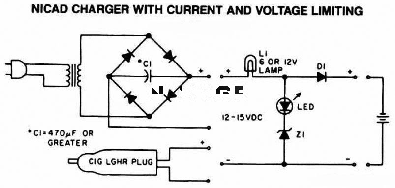
The following diagram is the schematic of a Ni-CAD battery charger circuit, which includes current and voltage limiting features to extend the battery's lifespan. The lamp L1 will illuminate brightly, and the LED will be off when the battery...
Schematic and description of a simple automatic NiMH battery charger circuit using IC 7805 with multiple selectable current options for charging. The described circuit is a straightforward automatic charger designed for Nickel-Metal Hydride (NiMH) batteries. It utilizes the IC 7805...
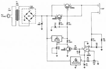
The charger's output voltage is adjustable and regulated, featuring an adjustable constant-current charging circuit that is compatible with most NiCad batteries. It is capable of charging a single cell or multiple series-connected cells with a maximum voltage of 18V....
Battery Indicator Circuit for the Caravan. This i-TRIXX circuit can prevent a lot of trouble for those who go on holiday in a caravan. It would be a significant damper on your holiday spirit when you are unprepared. The Battery...
This discussion assists in selecting the most appropriate microprocessor supervisor integrated circuit (IC) for specific applications and provides solutions for various common supervisory issues encountered with microprocessors. Microprocessor supervisor ICs are critical components in ensuring the reliable operation of microprocessor-based...

This circuit was created for digital cameras. It's known the digital cameras have considerable power consumption. For example, my camera Minolta E223 requires approximately 800 mA. In practice, a mains power supply or high capacity NiMH accumulators (batteries) can...