
HIGH PERFORMANCE VIDEO MIXER

The described circuit is a fundamental component in video processing, particularly in the context of analog video systems. The integration of H sync, V sync, and video signals is crucial for maintaining proper synchronization between the displayed image and the video source.
Transistor T2 plays a pivotal role in the mixing process, where it combines the synchronization signals to ensure that the timing of the video display aligns accurately with the incoming video data. This mixing is essential for preventing issues such as tearing or misalignment in the displayed image.
Transistor T1, acting as an emitter-follower, provides a high input impedance and low output impedance, which is beneficial for buffering the mixed signal. This configuration allows the circuit to drive subsequent stages without loading down the previous stage, thus preserving signal integrity. The emitter-follower configuration is advantageous in applications where signal isolation is necessary, and it helps to maintain the fidelity of the video signal.
The circuit's bandwidth capability of up to 25 MHz indicates its suitability for standard video resolutions, making it effective for various applications including television broadcasting and video conferencing systems. The design considerations for achieving this bandwidth include careful selection of components and layout to minimize parasitic capacitance and inductance, which can adversely affect performance.
Overall, this circuit exemplifies a critical aspect of video signal processing, where synchronization and signal integrity are paramount for delivering high-quality video output.This circuit mixes H synch. V synch. and actual video. T2 mixes the synch, while T1 serves as an emitter-follower. Bandwidths of up to 25 MHz are typical for this circuit. 🔗 External reference
Related Circuits
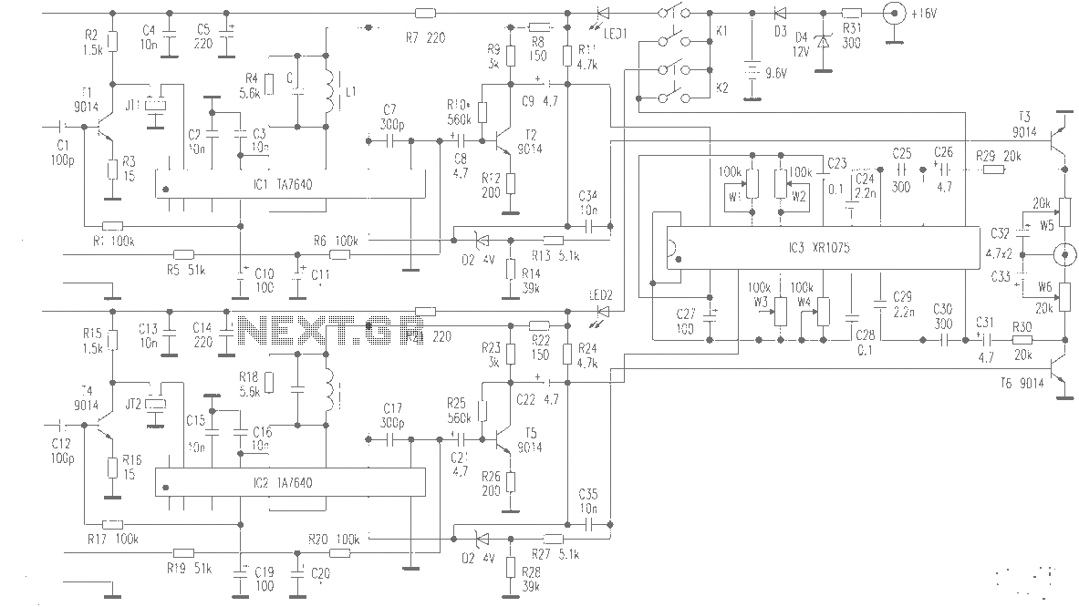
The production of high-quality wireless microphones is a common aspiration among enthusiasts, but achieving a high-performance receiver is challenging. This project explores the use of salvaged FM radio cassette players to enhance an XR1075 audio processor, leading to the...
As with any audio mixer circuit, a slight loss is always introduced. The final summing amplifier has a gain of 2 or 6dB to overcome this. The input line level should be around 200mV RMS. The mic inputs are...
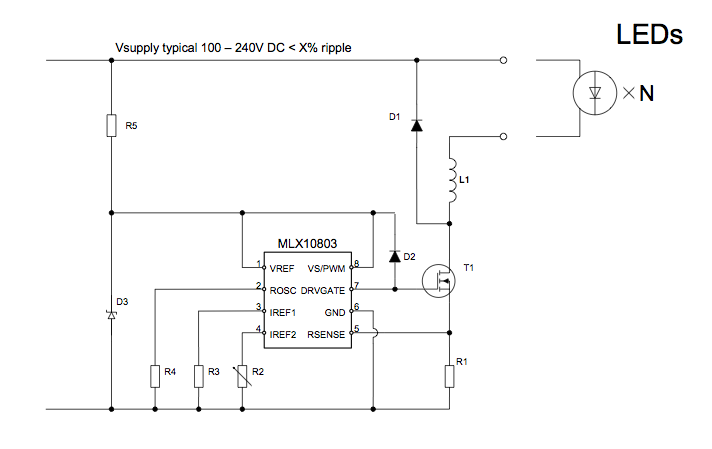
The applications outlined in this document pertain to driving high-power LED diodes. The circuits described can also be utilized in other applications with similar requirements, as long as they adhere to the specifications of the MLX10803. This is a...
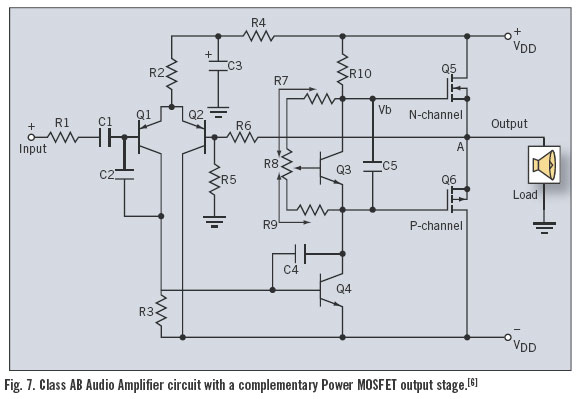
Utilizing the latest advancements in trench and polar power MOSFET technologies, both trench and polar P-Channel power MOSFETs have been developed that maintain all the characteristics of comparable N-Channel power MOSFETs, including rapid switching, voltage control, ease of paralleling,...
The objective of this project was to design a compact portable mixer powered by a 9V PP3 battery, while ensuring high-quality performance. The mixer consists of three primary modules, which can be customized in quantity and arrangement to meet...
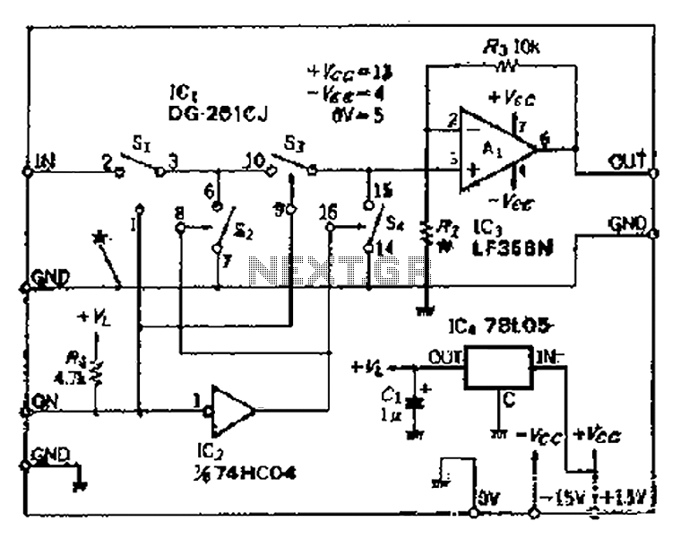
Analog switches SL and SA disconnect the inverted logic signal to terminal 2. S1 and S4 are turned on, allowing capacitance between S1 and S8 to couple. S2 and S4 shunt with an on-state resistance ranging from 50 to...