
High speed data switch circuit

This printer sharing circuit utilizes a simple architecture to facilitate the connection of multiple printers to a single output. The core functionality hinges on the Enable A and Enable B lines, which control the routing of data from the respective input sets (A1-A4 and B1-B4) to the output lines (O1-O4). The high output impedance necessitates the incorporation of buffers or drivers to ensure signal integrity, particularly over longer distances where capacitance and resistance in the cabling could degrade performance.
The circuit design allows for flexibility in the configuration of inputs and outputs. By employing logic gates or multiplexers, the system can be expanded to support additional input sets, making it adaptable for various applications. The fast switching capability of the 1N4148 diode ensures that data can be transmitted quickly, minimizing delay, which is critical in printer data communication.
In practical applications, care must be taken to avoid excessive loading on the output lines. The recommendation to use drivers is essential when interfacing with long printer cables, as the inherent capacitance and resistance of the cables can create signal degradation. Therefore, the implementation of suitable driver circuits will enhance the performance and reliability of the printer sharing device, ensuring that it can operate effectively in diverse environments.
Overall, this circuit serves as a foundational model for printer sharing solutions, demonstrating key principles of electronic design, including impedance matching, signal routing, and the importance of component selection in achieving desired performance characteristics.This circuit is a small representation of a very low cost printer sharer i made very long ago. This is as much i can remember of the basic ideas behind the product. I used to pot the product in epoxy with a black dye and sold a few, they sort of served the purpose. Output impedance of this circuit is high, sink is 220K source is 3.9K+ so use some buffers or drivers at Output. when Enable A is at float-high impedance or low the output O1-O4 is not influenced by A1-A4 inputs. If Enable A is made logic high or 5V then A1-A4 is available at O1-O4. By turning Enable A or Enable B high, you can route the data A1-A4 or B1-B4 to the output O1-O4, you can also mix data and you can expand to any number of input sets or data width.
1N4148 is fast, 4nS, that makes this data switch quite fast. This circuit cannot drive long printer cables without drivers. They will load the output. 🔗 External reference
Related Circuits
This is a 3 Band Equalizer circuit designed to control the treble, midrange, and bass frequencies. The circuit utilizes a single operational amplifier (op-amp). The 3 Band Equalizer circuit serves to enhance audio signals by allowing users to adjust specific...
This report outlines the operation and adjustment of a Phase Locked Loop (PLL) hum cancellation circuit designed to reduce residual hum from amplifiers. This circuit is particularly useful for Directly Heated Triode (DHT) amplifiers with AC-operated filaments, where a...
The two circuits below illustrate opening a relay contact a short time after the ignition or light switch is turned off. The capacitor is charged and the relay is closed when the voltage at the diode anode rises to...
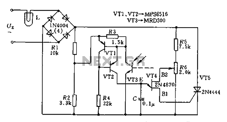
The circuit is designed to stabilize the brightness of lamp L using a thyristor-based AC automatic voltage regulator. The thyristor T5 is connected diagonally across the bridge circuit. The trigger pulses are generated by components VT1, VT2, and VT3,...
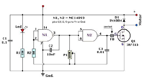
A quad 2-input NAND Schmitt trigger circuit can be designed using the MC14093 CMOS type IC, which serves as a simple pulse width modulation (PWM) controller electronic project. This PWM controller is straightforward and requires only a few external...
The following circuit illustrates the use of a 555 integrated circuit (IC) for an infrared (IR) remote control extender circuit. Features include support for 850 nm and 950 nm signal wavelengths, along with the capability to generate control pulses. The...