
High-voltage isolation switch operation display circuit

High-voltage isolation switches play a critical role in electrical safety by preventing accidental connections that could lead to arcing and short-circuit conditions. The use of mechanical or electrical interlock devices is essential in high-voltage switchgear to ensure the proper operational sequence is maintained. This prevents the isolation switch from being engaged while the circuit breaker is still closed, which could otherwise lead to dangerous scenarios.
The operation display system enhances safety by providing visual feedback regarding the status of the isolation switch. The auxiliary contacts (QF) of the circuit breaker are utilized to monitor the state of the circuit breaker, ensuring that the isolation switch can only be operated when it is safe to do so. The photosensitive resistor (RL) serves as a feedback mechanism, detecting the position of the operating handle and ensuring that it is in the correct position before any operation can occur.
The display lamp (H) serves as a critical safety feature, alerting operators to any illegal operations or incorrect settings. This lamp is prominently placed on the cabinet door for easy visibility, ensuring that personnel can quickly ascertain the status of the isolation switch and take appropriate action if necessary. The integration of these safety features into high-voltage isolation switch designs is paramount for maintaining operational integrity and protecting both equipment and personnel in high-voltage environments. As we all know, high-voltage isolation switch is not allowed to meet with a load that would otherwise produce arc, causing a short between the high voltage bus road accident, e ndanger the equipment and personal safety. Therefore, high voltage switchgear are taking mechanical or electrical interlock device type, and only when high pressure circuit breaker, disconnecting switch to pull off; the circuit breaker in the closing position, must not be co-isolation switch. Operating sequence order can not be reversed. In order to avoid misuse of the accident, but also made high-voltage isolation switch operation display, the principle of the circuit shown in Figure 13-114.
Figure, QF of high voltage circuit breaker normally open auxiliary contacts; RL is photosensitive resistance, installed in the isolation switch operating handle; H display lamp, an outer cover that read illegal operation, non-suit words, installed in the cabinet door .
Related Circuits
This circuit utilizes two quad op-amps to create an eight LED audio level meter. The op-amp employed in this circuit is the LM324, a widely used integrated circuit that is readily available from numerous electronic component suppliers. The 1K...
WB5LUA described GaAsFET preamplifiers for several microwave bands, which included an active bias circuit for the GaAsFET. Although newer devices have been introduced that offer improved performance, they require different bias points with varying currents and voltages. Modifying the...
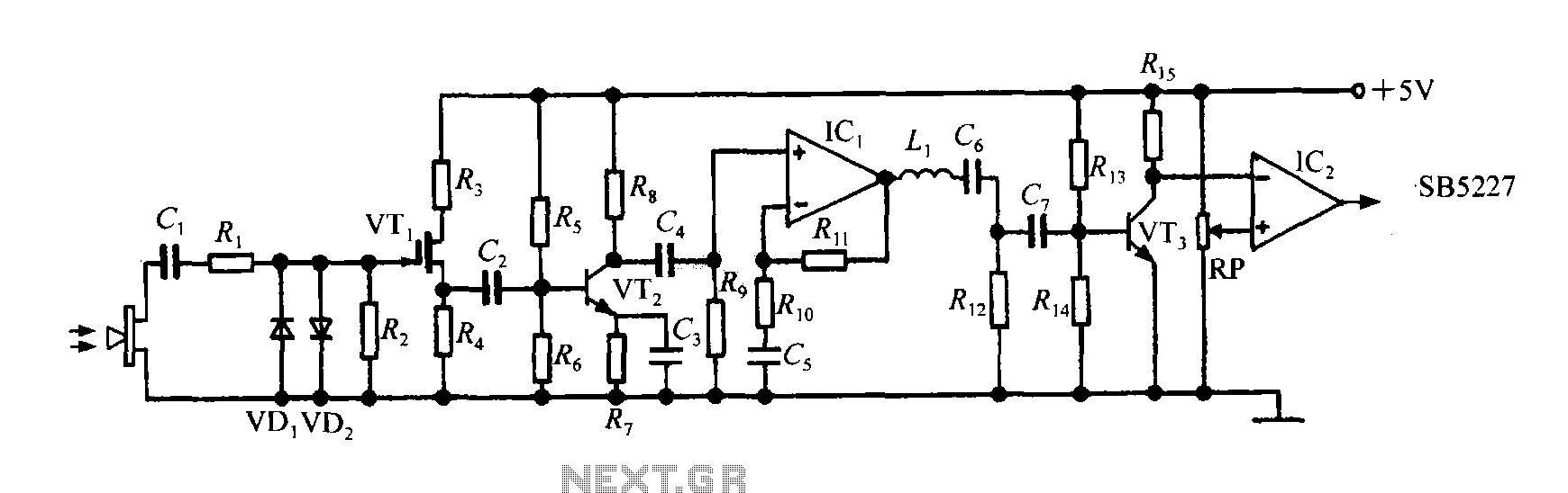
The SB5227 ultrasonic signal output is very weak and must be amplified via a power amplifier for effective transmission. A typical transmission circuit is illustrated in the accompanying figure. The SB5227 ultrasonic signal is sourced from output pin 10,...
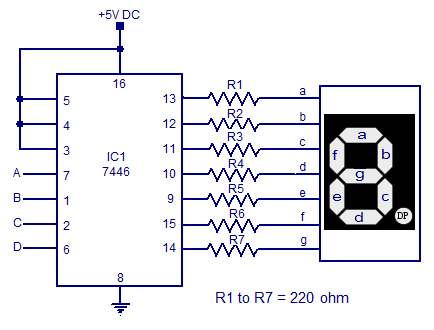
7-segment display driver circuit based on the 7446. This circuit includes a seven-segment display system and a 7-segment decoder/driver, capable of sinking and sourcing current for the display. The 7446 is a BCD (Binary-Coded Decimal) to 7-segment latch/decoder/driver that facilitates...
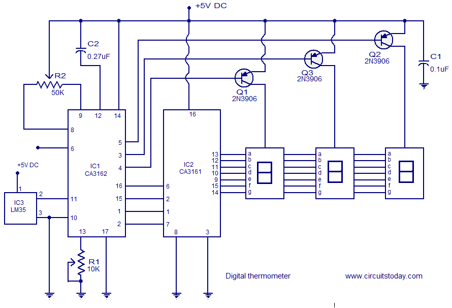
A simple digital thermometer circuit without a microcontroller and featuring a seven-segment LED readout is presented. The circuit utilizes three integrated circuits (ICs): CA3162, CA3161, and LM35. The CA3162 is a monolithic analog-to-digital (A/D) converter with a BCD output....
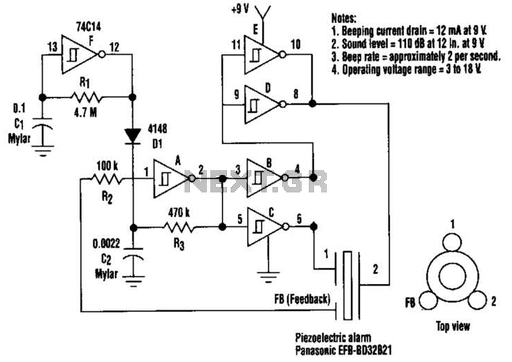
This circuit generates a loud sound of 110 dB using a 9 V power supply. It incorporates a single 74C14 (CD40106B) CMOS hex inverting Schmitt-trigger IC, which is utilized with a piezoelectric device that includes a feedback terminal. The...