
High Voltage Solid State Flyback Driver

The high voltage flyback driver circuit is designed to efficiently convert low voltage DC into high voltage pulses suitable for driving flyback transformers. The circuit typically utilizes a transistor as the main switching element, which is responsible for rapidly turning the current on and off in the primary winding of the flyback transformer.
To construct this circuit, essential components include a high-voltage flyback transformer, a suitable N-channel MOSFET or BJT transistor, resistors for current limiting, capacitors for filtering, and diodes for flyback protection. The transistor operates in a switching mode, allowing for rapid energy storage in the transformer’s magnetic field during the on-state and releasing it as high voltage during the off-state.
The schematic representation of the circuit will include the power supply input, the transistor with its gate/base drive circuitry, the flyback transformer, and the output stage. The design should incorporate feedback mechanisms to ensure stable operation and prevent over-voltage conditions, which can damage the components.
Additionally, the flyback driver may feature a snubber circuit to protect against voltage spikes and improve efficiency. The layout should be carefully designed to minimize parasitic inductances and capacitances, which can adversely affect performance. Proper heat dissipation methods, such as heat sinks or cooling fans, should also be considered to maintain the operational integrity of the transistor during high-frequency switching.
Overall, this high voltage flyback driver circuit is an effective solution for applications requiring high voltage generation, such as in CRT displays, gas tube lighting, or high-voltage ignition systems.Fully illustrated and schematised plans for a high performance, easy to build transistorised high voltage flyback driver.. 🔗 External reference
Related Circuits

R1 controls the trip-point of the circuit. adjust it accordingly. to reverse the logic (have the led light up when the battery has at least X amount of power,) connect the led to ground through R4. More: all resistors...
The SM5021 series consists of crystal oscillator module ICs fabricated using NPC's Molybdenum-gate CMOS technology. These ICs integrate high-frequency, low current consumption oscillator and output buffer circuits. They feature highly accurate thin-film feedback resistors and high-frequency capacitors, which eliminate...

These novel relay driver circuits can activate a relay with a coil voltage rating that is double the Vcc. After activation, the relay armature is held in place. The relay driver circuits described are designed for applications requiring the control...
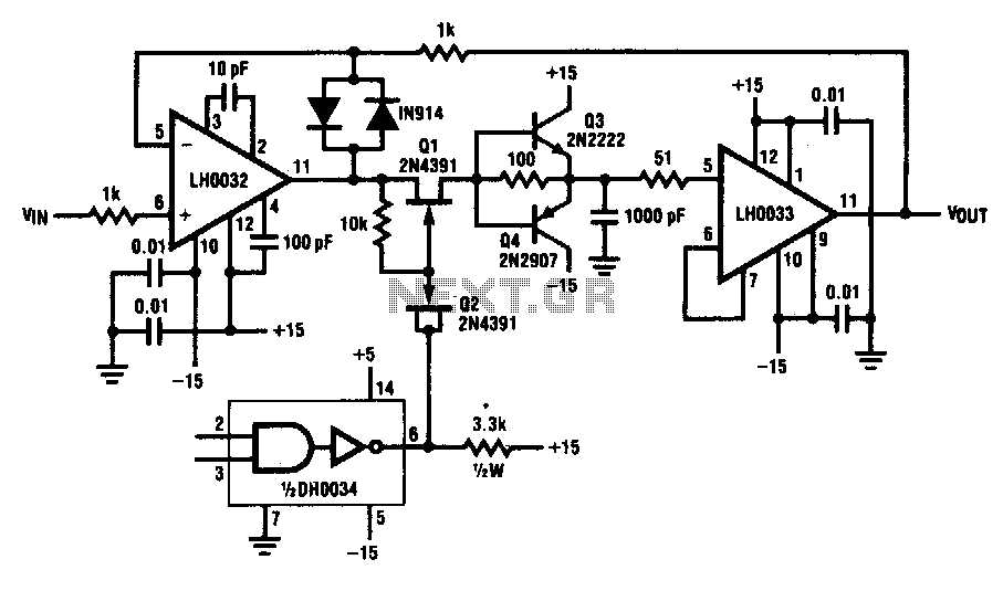
This circuit demonstrates a 10 V acquisition time of 900 ns with 0% accuracy and a droop rate of only 100 µV/ms at an ambient temperature of 25°C. A faster acquisition time can be achieved by using a smaller...
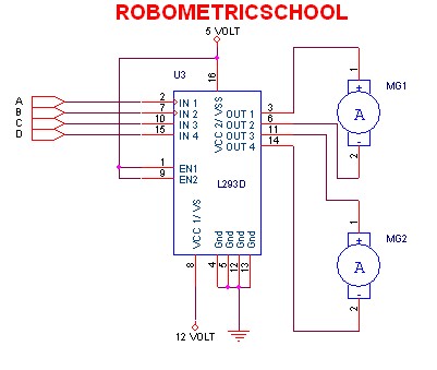
The electronic schematic of a DC motor driver using the L293D, as illustrated in Figure 2, enables the control of two DC motors continuously. It allows for one motor to rotate clockwise while the other rotates counterclockwise. Additionally, all...
In various electronics-level adjustments, such as LED drivers for LCD panel backlight controls, the AD5228 can be utilized. A manually adjustable LED driver is illustrated. The AD5228 is a dual-channel, digitally controlled potentiometer (DCP) that can be employed in applications...