
Home security monitor system
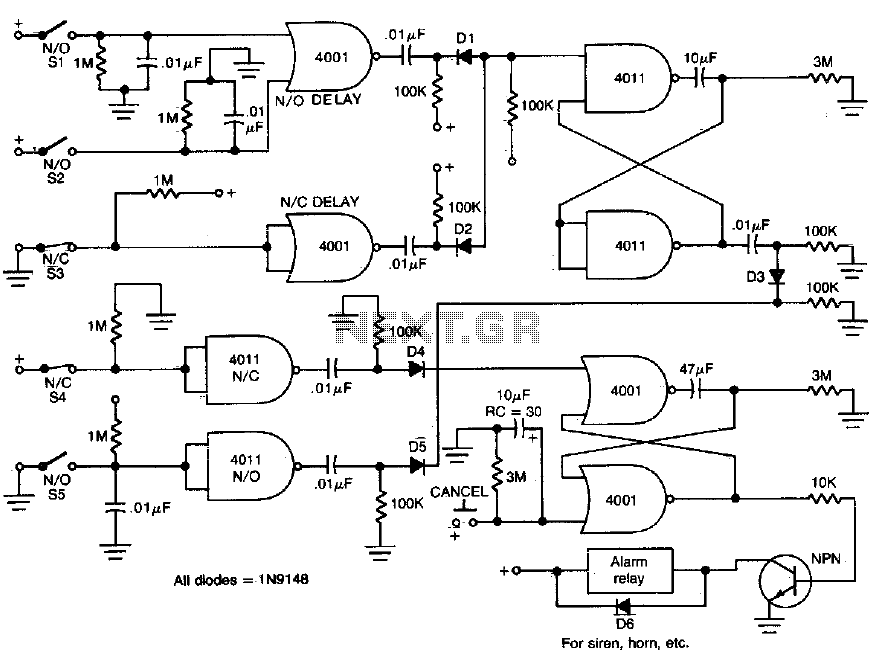
The described circuit functions as a delay timer for activating an alarm system, utilizing both normally open (NO) and normally closed (NC) contacts. The main components include three switches (SI, S2, S3) that implement the delay mechanism, allowing the alarm to be triggered after a specified period of 30 seconds. This delay feature is essential in scenarios where a temporary interruption is allowed before the alarm is activated, providing users with a grace period to cancel the alarm if necessary.
The NO contacts (SI, S2, S3) will close after the 30-second delay, completing the circuit and activating the alarm. Conversely, the NC contacts remain closed during the delay period and will open once the alarm is triggered, effectively signaling the alarm condition. The immediate action of switches S4 and S5 ensures that certain conditions can trigger the alarm without delay, providing a dual-layered response mechanism for different scenarios.
Additionally, the CANCEL switch is a critical component that allows users to reset the alarm system. When engaged, the CANCEL switch interrupts the circuit, returning the system to its initial state and preventing the alarm from sounding. This feature enhances user control over the alarm system, allowing for manual intervention without the need for waiting for the delay to expire.
Overall, the circuit design emphasizes user flexibility and responsiveness, ensuring that alarm conditions can be managed effectively while also providing an automatic delay feature for enhanced usability.This circuit provides normally open (NO) and normally closed (NC) contacts SI, S2, and S3 to turn on the alarm after a 30 second delay. S4 and S5 operate instantly The CANCEL switch resets the alarm. 🔗 External reference
Related Circuits
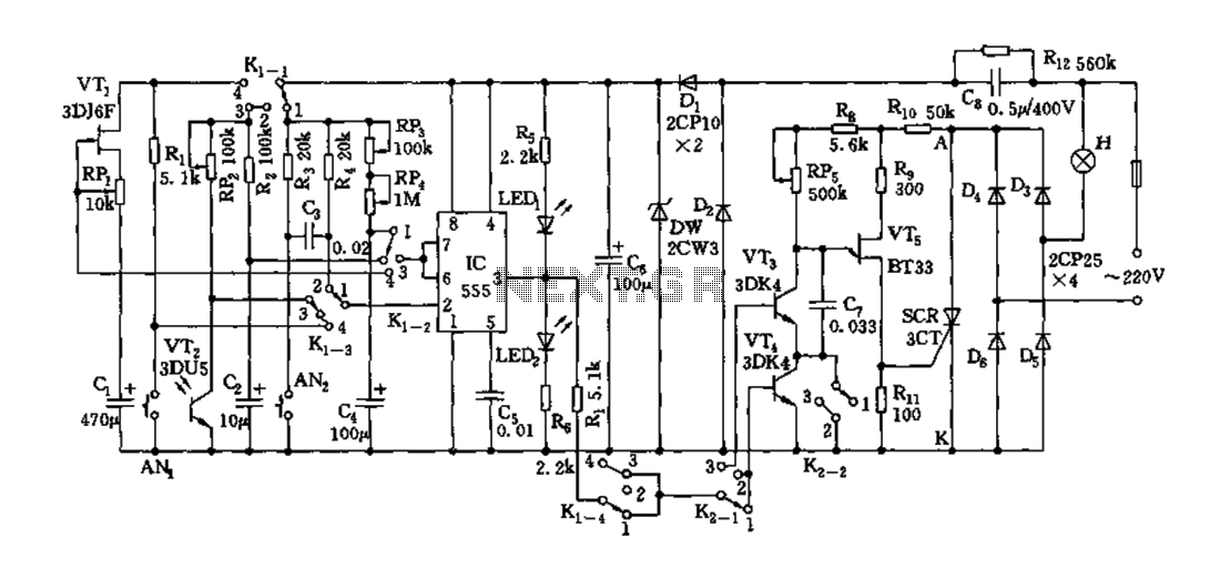
Depending on the external circuit connection, the 555 timer can be configured for various modes such as start delay, trigger delay, multi-harmonic oscillation, and other operational conditions. It functions as a versatile tester with the inclusion of some RC...

This circuit utilizes a small AC current transformer from Magnetek to generate an isolated voltage that is proportional to the AC current flowing through the primary winding. The transformer features a single-turn primary with a low resistance of 0.001...
Due to the huge interest in this project, I have just recently finished the NEW schematics. The older schematics were scanned and pretty poor quality. These new ones should make it considerably easier to recognize the parts used for...
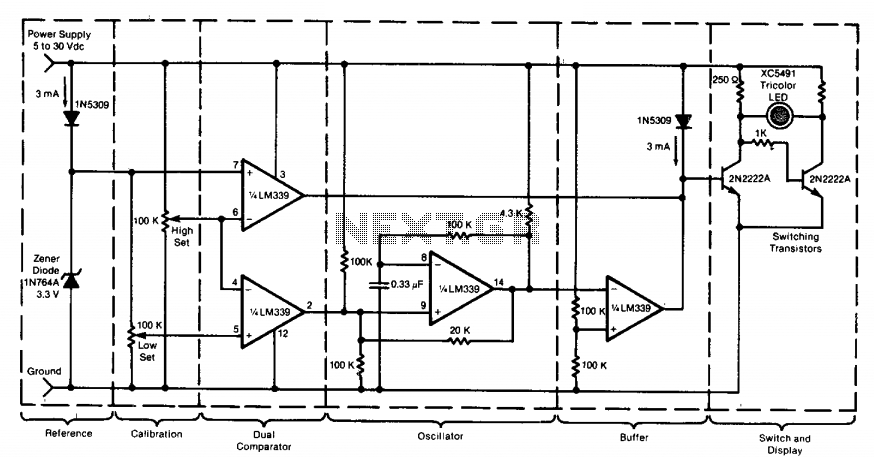
This circuit utilizes a tricolor LED display to signify acceptable and unacceptable output voltages. One LED indicates the upper voltage limit, while another indicates the lower voltage limit. When the monitored voltage exceeds the maximum set point, the LED...

One of the goals of Movable Party is to provide an interactive experience for audiences and participants. Power will be generated from a hub motor attached to the rear wheel of each bike, with the speed of the rear...
This device is designed to capture images of moving objects by activating a camera or flashgun when one or two light beams are interrupted. Originally intended for photographing insects in flight, it can also be utilized for projectiles and...
Warning: include(partials/cookie-banner.php): Failed to open stream: Permission denied in /var/www/html/nextgr/view-circuit.php on line 713
Warning: include(): Failed opening 'partials/cookie-banner.php' for inclusion (include_path='.:/usr/share/php') in /var/www/html/nextgr/view-circuit.php on line 713