
Honda Motorcycle CB750F Wiring Diagram

The electrical wiring connection diagram for the Honda Motorcycle CB750F serves as a crucial reference for understanding the intricate relationships between various components within the motorcycle's electrical system. The diagram provides a visual representation of how each part is interconnected, facilitating troubleshooting and maintenance.
Key components illustrated in the diagram include the turn signal indicators, which are vital for signaling direction to other road users. The oil pressure warning light serves as an important safety feature, alerting the rider to potential engine oil issues. The neutral indicator is essential for confirming that the transmission is in a neutral state, preventing unintended movement when starting the engine.
Additional components such as the tachometer and speedometer lights provide essential feedback to the rider regarding engine RPM and vehicle speed, respectively. The headlight is a critical safety feature for visibility during night riding or low-light conditions. The horn and its button ensure that the rider can alert others of their presence on the road.
Switches like the clutch switch and front stop switch are integral for the safe operation of the motorcycle, allowing for safe engagement and disengagement of the engine power. The turn signal control switch and dimmer switch enhance rider control over lighting and signaling functions.
The ignition switch and starter motor are pivotal for engine start-up, while the battery provides the necessary power for electrical systems when the engine is not running. The alternator and regulator/rectifier work together to maintain the battery charge and supply power to the electrical systems while the engine is operational.
Fuses are included in the diagram as protective elements, ensuring that the electrical system is safeguarded against overloads. The connection of the spark units, ignition coils, and pulse generator are critical for the ignition system, ensuring proper engine operation.
Understanding the color codes associated with each wire in the diagram is essential for accurate connections and repairs, as it helps to prevent errors during assembly or troubleshooting. Overall, this wiring diagram is an invaluable tool for both technicians and motorcycle enthusiasts alike, providing a comprehensive overview of the electrical system of the Honda Motorcycle CB750F.The following picture shows the electrical wiring connection diagram for Honda Motorcycle CB750F. It shows the connection between Honda parts such as the right turn signal indicator light, oil pressure warning light, neutral indicator, high beam indicator, turn signal indicator, tachometer lights, speedometer lights, turn/signal running lights, he adlight, turn signal/running light, horn and horn button, clutch switch, front stop switch, turn signal control switch, dimmer switch, engine stop switch, spark units, neutral switch, oil pressure switch, rear stop switch, fuses, ignition switch, starter motor, battery, turn signal right rear, tail and brake light, turn signal left rear, regulator/rectifier, alternator, ignition coils, pulse generator, spark plugs, and also the color code. 🔗 External reference
Related Circuits
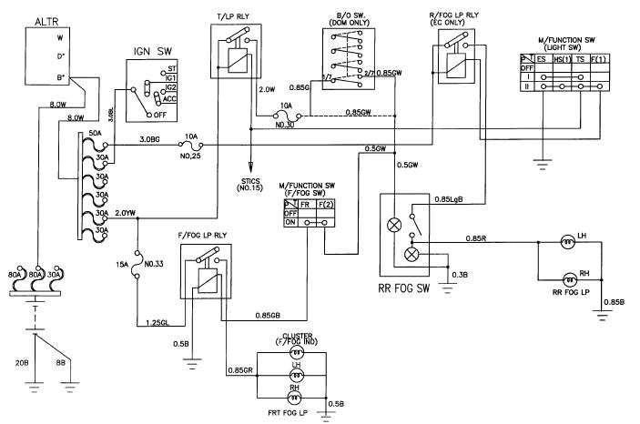
The schematic for the front and rear fog lamps of the Daewoo Korando is illustrated in the accompanying figure. It details the connections and wiring between various components of the fog lamp system, including the alternator, ignition switch, taillamp...
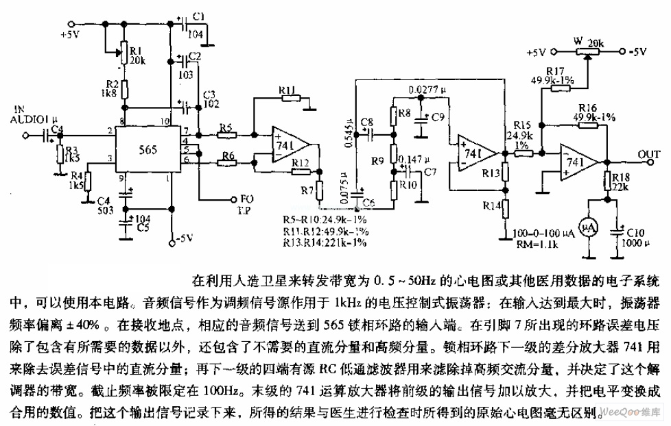
The circuit is designed for satellite transmission of ECG signals with a bandwidth range of 0.5 to 50 Hz, as well as other medical data within electronic systems. An audio signal serves as the FM signal source, which is...
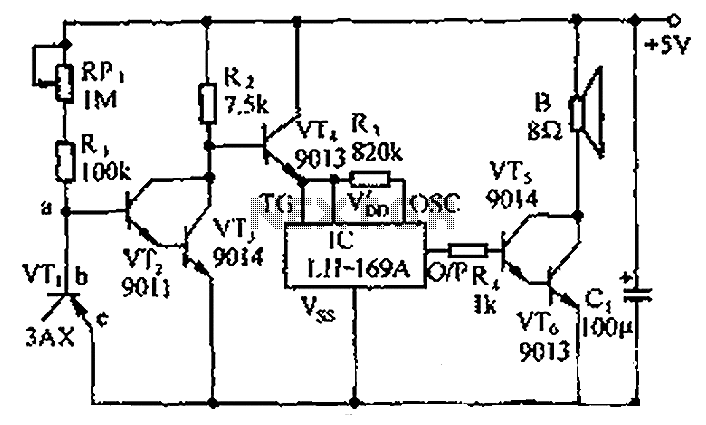
The 555 timer on the right is configured as an alarm sound generator, while the second 555 timer on the left functions as a 1 Hz astable multivibrator. The output from the left timer modulates the frequency of the...
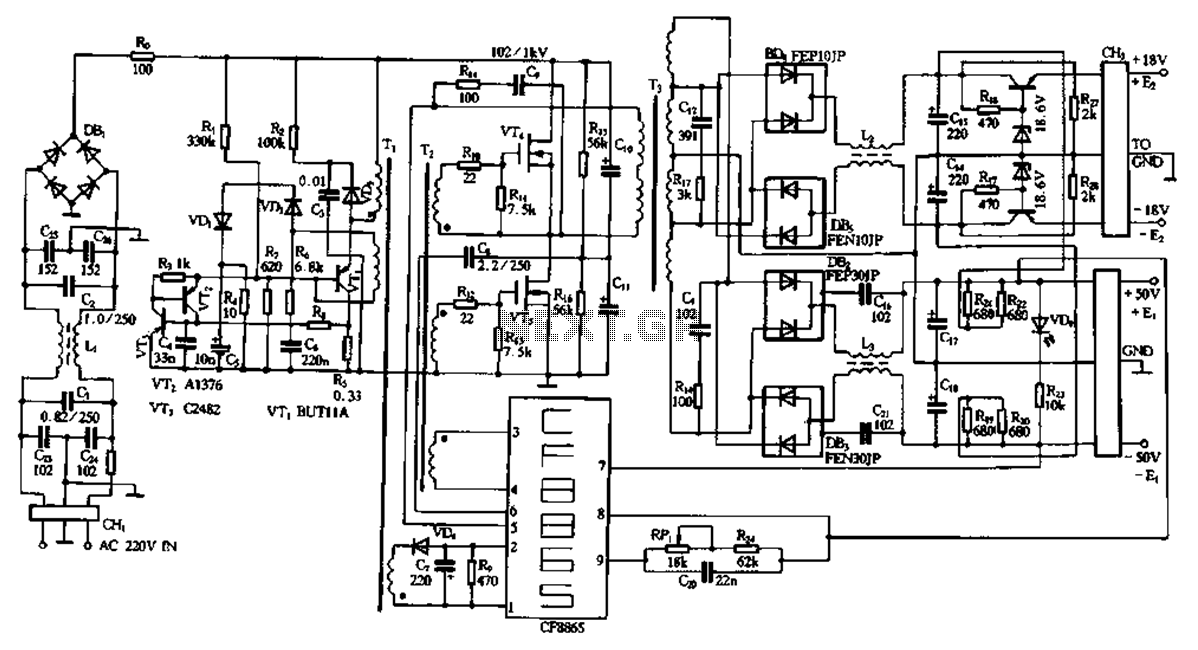
This document describes a specific module utilizing the CF8865 switching power supply circuit, which employs the integrated control module CF8865. In the figure, transistors VT4 and VTs are controlled by the excitation transformer Tz. The output is processed through...
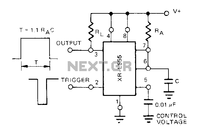
The Exars XR-L555 circuit has a typical power consumption of 900 W and operates with a power supply voltage of 5V. It is a micro-power circuit that can be used as a direct replacement for the standard 555 timer....
The circuit consists of a temperature sensor, electronic switches for temperature control, and a vocal language output system. During hot summer months, the central processing unit (CPU) of PCs frequently experiences overheating. The circuit, with VT1 positioned near the...