Honda VT750C Ace Electrical
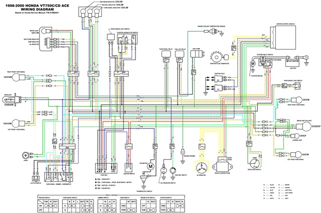
The following circuit illustrates the electrical circuit diagram for the Honda VT750C Ace. Features include a 745cc engine with a 52-degree V-twin configuration and two 36mm constant velocity carburetors.
The Honda VT750C Ace electrical circuit diagram serves as a crucial reference for understanding the electrical components and their interconnections within the motorcycle. The circuit encompasses various essential elements such as the ignition system, lighting, and battery management.
The ignition system typically includes components such as the ignition coil, spark plugs, and the electronic control unit (ECU). The ECU is responsible for managing the timing and firing of the spark plugs to ensure optimal engine performance. The circuit diagram will indicate the connections between these components, illustrating how the electrical signals are transmitted to initiate combustion.
The lighting system is another vital aspect of the circuit, comprising headlight, taillight, turn signals, and instrument panel lights. Each lighting component is connected through a series of switches and relays that control their operation. The circuit diagram will provide details on the wiring paths, including the fuses that protect the system from overloads.
The battery management section of the diagram will outline the connections to the battery, including the charging system, which consists of the alternator and voltage regulator. This section is crucial for ensuring that the battery remains charged during operation and can supply power to the electrical components when the engine is not running.
Overall, the Honda VT750C Ace electrical circuit diagram is an essential tool for maintenance and troubleshooting, allowing technicians and enthusiasts to understand the layout and function of the motorcycle's electrical system comprehensively.The following circuit shows about Honda VT750C Ace Electrical Circuit Diagram. Features:745cc 52-degree, two 36mm constant velocity carburetors, .. 🔗 External reference
