
How does an astable multivibrator LED blinking circuit work

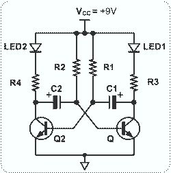
The circuit described involves a sequential LED blinking mechanism, which can be achieved through a simple astable multivibrator configuration using transistors. The primary components typically include two light-emitting diodes (LEDs), a capacitor, resistors, and two NPN transistors.
In this configuration, the capacitor is crucial for timing. When the circuit is powered, the capacitor begins to charge through a resistor. This charging process causes the voltage across the capacitor to rise gradually. Once the voltage reaches a certain threshold, it turns on the first NPN transistor, allowing current to flow through the first LED, causing it to illuminate.
As the capacitor continues to charge, it eventually reaches a point where it can no longer sustain the first transistor's conduction, causing the transistor to turn off. This results in the first LED turning off. The discharge path for the capacitor is typically through the second transistor, which is connected in such a way that when the first transistor turns off, the second one turns on, allowing current to flow through the second LED.
The timing of the LED blinking is determined by the values of the resistors and the capacitor used in the circuit. By adjusting these components, one can control the rate at which the LEDs blink in sequence. The transistors serve as electronic switches that control the flow of current to each LED based on the charge state of the capacitor, thereby enabling the sequential blinking effect. This arrangement not only provides a visual indication of the circuit's operation but also serves as a fundamental demonstration of capacitor charging and discharging principles in electronics.Blinks 2 LEDs timely in sequence. Will somebody explain its working I know that capacitor will charge and during the charging the LED will off and whenthey discharge they will on the LED. But why transistor are there 🔗 External reference
Related Circuits
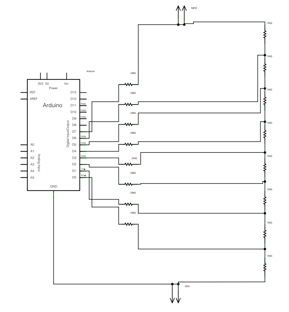
The main concept is to space the time intervals to increment the DAC output values. There are 256 levels since there are 8 digital outputs from the Arduino board. Therefore, for an 8-bit resolution and a 50-second ramp time,...
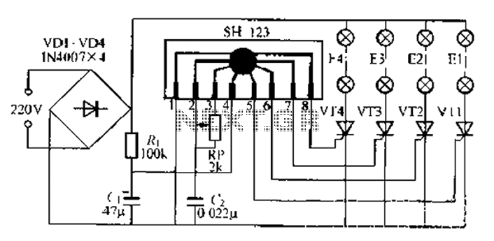
A water Happy Valley-type four flashing lights string controller, electric bollard is designed for use with a type J Ding Japanese lantern. The circuit employs a specific integrated circuit (IC) utilizing CMOS technology. It features a black soft cream...

The TDA1020 is a monolithic integrated 12 W audio amplifier housed in a 9-lead single in-line (SIL) plastic package. Although it is designed primarily for car audio applications, it can also be utilized in various other audio applications. The TDA1020...
This circuit is straightforward and easy to construct, utilizing two transistors as active components along with several passive components such as resistors, capacitors, and two LEDs. The circuit employs the MPS2222 transistor, though any NPN type transistor can be...
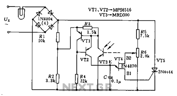
The circuit utilizes a thyristor-based AC automatic voltage regulator to stabilize the brightness of lamp L. A diagonal line connects the thyristor to the T5 bridge. The trigger pulse for the thyristor is generated by a single-junction transistor, VT4....
This single transistor audio mixer is utilized in an amplifier circuit design featuring a base-driven transistor, with its emitter being current-controlled. This audio mixer circuit employs a single transistor to facilitate the mixing of audio signals. The transistor operates in...