
Unit DisplayCircuit With LM3915 IC

The upgraded circuit enhances the functionality of the original Simple Volume Unit Display by incorporating additional power handling capabilities for audio input signals. This improvement allows for a more robust performance in displaying audio levels, making it suitable for applications where higher audio signal strengths are encountered.
The circuit typically includes various components such as resistors, capacitors, diodes, and operational amplifiers, each playing a crucial role in the overall operation. Resistors are used for current limiting and voltage division, ensuring that the input signals are appropriately scaled for processing. Capacitors may be included to filter out noise and stabilize the voltage levels, contributing to a more accurate display of the audio signal.
Operational amplifiers can be employed to amplify the audio signal before it is processed by the volume unit display. This amplification is critical in achieving a clear and precise representation of audio levels, especially in environments with varying signal strengths. Additionally, the circuit may incorporate LED indicators or LCD displays to visually represent the audio levels, providing immediate feedback to users.
Power supply considerations are also essential in this design. The circuit should be powered by a stable voltage source capable of delivering sufficient current to support the enhanced components, particularly the operational amplifiers and any display elements. Proper grounding and layout techniques should be employed to minimize interference and ensure reliable operation.
In summary, this upgraded circuit offers a significant improvement over the original design, providing enhanced power handling for audio inputs and a more accurate and responsive volume unit display.this is an upgrade circuit from Simple Volume Unit Display Circuit Diagram 1 with more addition power for the audio input.. Component: Resistor, .. 🔗 External reference
Related Circuits
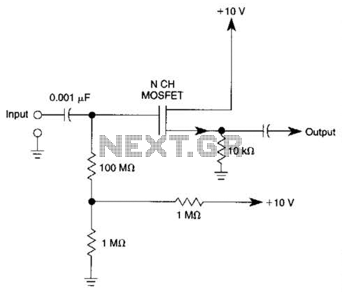
Biasing methods for an N-channel MOSFET to form a unity-gain noninverting amplifier or source-follower. The N-channel MOSFET can be utilized in various configurations, with one common application being the unity-gain noninverting amplifier, also known as a source-follower. In this configuration,...
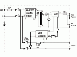
This circuit illustrates the SSR (Solid State Relay) Power Control Unit Circuit Diagram. Features: The SSR control box supplies the control voltage for the relay. Component: . The SSR Power Control Unit Circuit is designed to provide efficient control of...
For several recent projects, a request was made to provide engaging and informative display units. A versatile unit was developed that can be utilized across different applications. It was designed for aesthetic appeal, capable of displaying both graphics and...
The consumer unit cupboard in some older houses is poorly illuminated. If a bell transformer is also situated in this cupboard, it can be utilized to provide emergency lighting using two high-current LEDs. These diodes are powered through a...
The function of the sound level display circuit is to enhance the appearance of an amplifier circuit or a radio player. It provides an impressive visual representation of audio levels. The sound level display circuit serves as a visual indicator...
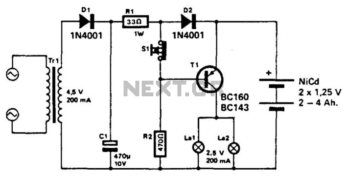
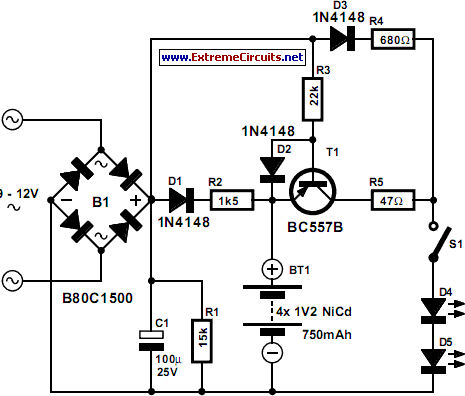
This unit utilizes a NiCad battery to supply power to an emergency lighting system. During a power failure, transistor T1 becomes forward biased, activating lamps L1 and L2. The batteries are typically maintained in a charged state. When the...