
How to change the range of voltage

In this project, the dsPIC microcontroller serves as the core processing unit, generating a Pulse Width Modulation (PWM) signal that regulates the speed of a DC motor. The PWM signal is characterized by its duty cycle, which determines the average voltage supplied to the motor. By adjusting the duty cycle, the effective voltage can be controlled, thereby varying the speed of the motor.
The L293D driver IC is utilized to interface between the dsPIC and the motor. This IC is designed to drive inductive loads such as motors, providing bidirectional control. It features built-in diodes for back EMF protection, which is essential for preventing damage to the microcontroller and the driver circuit when the motor is turned off.
To achieve a broader range of speed control, it may be necessary to implement an additional feedback mechanism. This could involve using an encoder to monitor the motor's actual speed and adjusting the PWM signal accordingly. The encoder provides real-time data, enabling closed-loop control that enhances speed accuracy and responsiveness.
In summary, the combination of a dsPIC microcontroller, PWM signal generation, and the L293D driver IC forms a robust foundation for motor control applications. By incorporating feedback mechanisms, the system can achieve precise control over motor speed across its entire operational range.Doing a project to use dsPIC as controller to output PWM signal to control motors. I can use driver IC (I used L293D actually) to simply let motors to rotate, but I cannot control the voltage range to control the motor to rotate with all range of speed. 🔗 External reference
Related Circuits
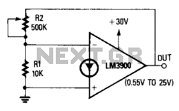
The non-inverting terminal of the operational amplifier (op-amp) is grounded, and the circuit utilizes the voltage at the inverting terminal as a reference. The voltage gain of the circuit is determined by the ratio of resistors R2 to R....

Voltage variations and power cuts adversely affect various equipment such as TVs, VCRs, music systems, and refrigerators. This simple circuit will protect costly equipment from high and low voltages and voltage surges when power resumes. It also produces a...
Buffering for the zener diode is achieved through the impedance matching and current amplifying features of the emitter follower, which draws less current from the zener. Buffering in electronic circuits is essential for ensuring that the performance of one component...

The LTC 4251B, LTC4251B-1, and LTC4251B-2 are negative voltage Hot Swap controllers that facilitate the safe insertion and removal of a board from a live backplane. Output current is regulated through three stages of current limiting: a timed circuit...
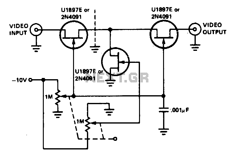
The tee attenuator offers optimal dynamic linear range attenuation of up to 100 dB, even at a frequency of 10.7 MHz with appropriate layout. The tee attenuator is a crucial component in RF and audio applications where signal integrity and...
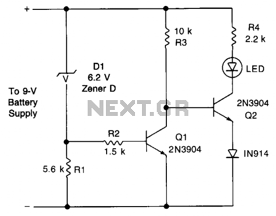
This circuit provides an early warning for battery discharge. A Zener diode (D1) is selected to indicate when the voltage falls below 9 V. If the supply voltage drops below 7 V, D1 will stop conducting, which will cause...