
Transistor Buffer for Zener Diode Voltage Regulator

Buffering in electronic circuits is essential for ensuring that the performance of one component does not adversely affect another, particularly in sensitive applications like zener diode voltage regulation. The emitter follower configuration, also known as a common-collector amplifier, serves as an effective buffer due to its high input impedance and low output impedance. This configuration allows the circuit to maintain the voltage level provided by the zener diode while minimizing the load it experiences.
In this setup, the zener diode regulates the voltage across its terminals, providing a stable reference voltage. The emitter follower, connected to the zener's output, takes this reference voltage and buffers it, allowing for higher current drive capabilities without drawing significant current from the zener itself. This is particularly important in applications where the zener diode needs to maintain its voltage regulation under varying load conditions.
The emitter follower's current amplification characteristics enable it to supply sufficient current to the load while keeping the zener diode operating within its specified parameters. This arrangement not only enhances the overall stability of the circuit but also improves the response time, making it suitable for dynamic applications where rapid changes in load current may occur.
In summary, utilizing an emitter follower to buffer a zener diode effectively combines the benefits of impedance matching and current amplification, ensuring reliable performance and improved efficiency in voltage regulation circuits.Buffering for the zener is provided by the impedance matching and current amplifying characteristics of the emitter follower and draw less current from it. To.. 🔗 External reference
Related Circuits
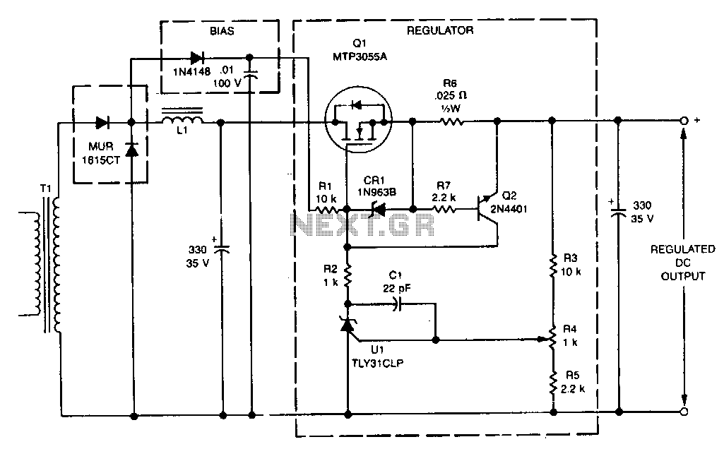
This linear post regulator provides 12 V at 3 A. It utilizes the TL431 reference (U1), which, without additional amplification, drives the gate of the TMOS MTP3055A (Q1) series pass regulator. A bias voltage is applied through resistor R1...

Transistors Q1 and Q2 are configured as a free-running multivibrator. The output at the emitter of Q2 drives the base of the common emitter amplifier Q3, which controls the lamp. This circuit configuration allows for independent variation of flash...
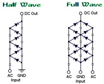
How to create a voltage multiplier using diodes and capacitors, capable of producing extremely high voltage. A voltage multiplier is a circuit that converts a lower AC or DC voltage into a higher DC voltage using a combination of capacitors...
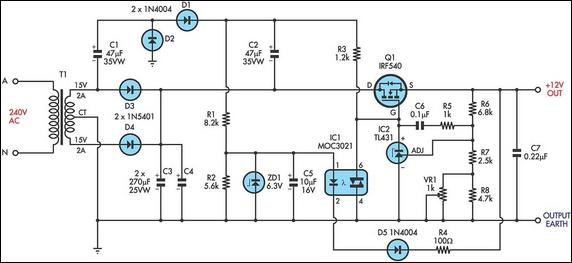
The circuit is a MOSFET-based linear voltage regulator capable of a voltage drop as low as 60mV at 1A. It utilizes a 15V-0-15V transformer and an IRF540 N-channel MOSFET (Q1) to provide a regulated 12V output. The gate drive...
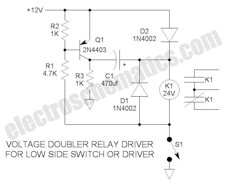
These novel relay driver circuits have the capability to activate a relay with a coil voltage rating that is double the supply voltage (Vcc). Once the relay is activated, the armature is maintained using Vcc, resulting in a significant...
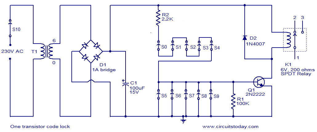
This is a simple electronic code lock circuit that can be easily constructed. The circuit consists of one transistor, a relay, and several passive components. Its simplicity does not compromise performance, and it functions effectively. The circuit operates as...