
how to make car battery charger
The 12 V battery charger circuit typically consists of several key components that work together to ensure efficient charging of the batteries. The primary components include a transformer, a rectifier, a voltage regulator, and a charging control circuit.
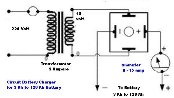
1. **Transformer**: The transformer steps down the input AC voltage to a lower AC voltage suitable for charging a 12 V battery. It is crucial to select a transformer with an appropriate rating to handle the current required for charging.
2. **Rectifier**: The rectifier converts the AC voltage from the transformer into DC voltage. A bridge rectifier configuration is often used, which consists of four diodes arranged in a bridge format. This configuration allows for full-wave rectification, providing a smoother DC output suitable for battery charging.
3. **Voltage Regulator**: To prevent overcharging and ensure that the battery receives a stable voltage, a voltage regulator is employed. Commonly used regulators include the LM7812 or similar linear voltage regulators, which maintain the output voltage at a constant level despite variations in input voltage or load conditions.
4. **Charging Control Circuit**: This circuit monitors the battery voltage and adjusts the charging current accordingly. It may include components such as resistors, capacitors, and possibly a microcontroller for more advanced control. The goal is to terminate the charging process once the battery reaches its full charge state, thereby prolonging battery life and preventing damage.
5. **Protection Features**: Additional protective components, such as fuses or circuit breakers, can be integrated into the design to safeguard against overcurrent conditions. Furthermore, heat sinks may be employed on the voltage regulator to dissipate excess heat generated during operation.
The overall layout of the circuit should be carefully designed to minimize noise and interference, ensuring stable operation. Proper PCB design techniques, such as short trace lengths and adequate grounding, should be implemented to enhance performance and reliability.Here is the circuit diagram of a simple and straight forward 12 V battery charger circuit with diagram. This circuit can be used to charge all type of 12V rechargeable batteries including car batteries and motorcycle batteries.
🔗 External reference
Related Circuits
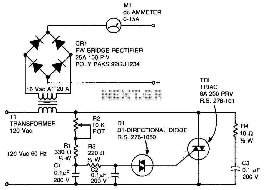
A diac is utilized in the gate circuit to enable operation for the signal applied to the gate. R1 sets a threshold level for triggering the triac. C3 and R4 are chosen to restrict the maximum charging current, forming...
Is the battery depleted, or is there an issue with the device? This question often arises when a battery-operated device, such as a Walkman, fails to power on. Before seeking professional repair services, it is advisable to first test...
A straightforward method for charging a battery using a higher voltage source is illustrated in the accompanying circuit diagram. The circuit requires only one resistor to establish the desired charging current, which can be determined by dividing the voltage...
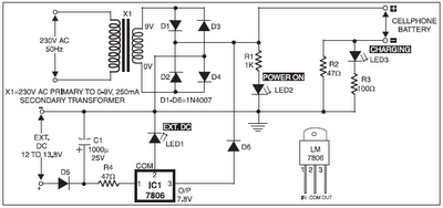
The 220V AC mains supply is downconverted to 9V AC by transformer X1. The transformer output is rectified by diodes D1 through D4 wired in bridge configuration, and the positive DC supply is directly connected to the charger's output...

According to current legislation in many countries, vintage cars must also be fitted with a fog lamp at the rear. In modern cars, there is a bit of circuitry involved in the integration of fog lamps. Fog lamps are essential...

This is a single-zone alarm system featuring independently adjustable Exit, Entry, and Siren Cut-Off timers. It is compatible with standard normally-closed input devices such as magnetic-reed contacts, foil tape, and passive infrared sensors (PIRs). A mains power supply can...