
Hydrophone Pre-Amplifier Circuit

A hydrophone operates by converting sound waves into electrical signals, making it an essential tool for underwater acoustics. The device typically consists of a sensitive transducer that is capable of detecting a wide range of frequencies, which is crucial for various applications such as marine biology, underwater communication, and seismic monitoring.
The construction of a hydrophone often includes a waterproof housing to protect the internal components from water damage. This housing is usually made from materials such as stainless steel or specialized plastics that can withstand high pressures found at greater depths. The transducer element itself may be piezoelectric, capacitive, or electromagnetic, depending on the design and intended frequency range.
In operation, sound waves traveling through the water induce vibrations in the hydrophone's transducer. These vibrations are converted into electrical signals that can be amplified and processed for analysis. The hydrophone's sensitivity and frequency response are critical parameters that determine its performance in capturing subtle underwater sounds, such as marine life communication or geological activity.
Hydrophones can be deployed in various configurations, including fixed installations on the seabed, towed arrays, or as part of autonomous underwater vehicles (AUVs). The choice of configuration often depends on the specific application and the environment in which the hydrophone will operate.
Overall, the design and functionality of hydrophones are pivotal in advancing underwater research and exploration, providing valuable data for scientists and engineers alike.Hydrophone is a tool like microphone, but this tool is used in the underwater environment. When used to pick up a sound on the air then this tool becomes less.. 🔗 External reference
Related Circuits
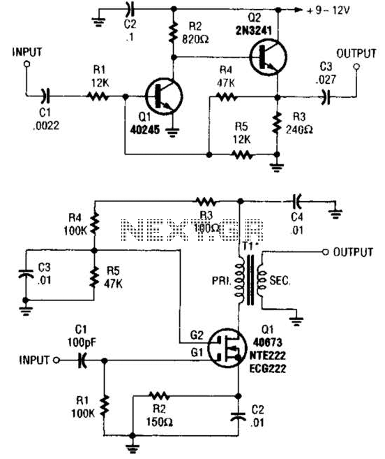
These two buffer/amplifiers have been effectively utilized with variable frequency oscillators (VFOs): one (depicted in A) is constructed using a pair of bipolar NPN transistors, while the other (illustrated in B) is designed around a dual-gate MOSFET. The first buffer/amplifier,...
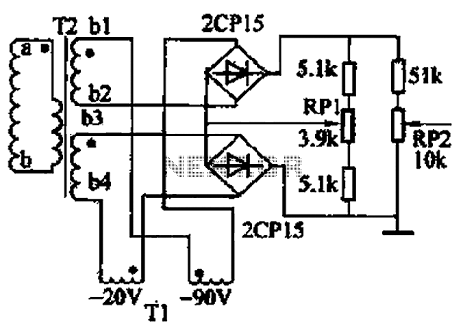
The closed-loop system consists of longitudinal and transverse components. The circuit operates as follows: a control circuit from the stepping motor CNC system issues a command, which the receiver detects. This signal is processed through a phase-sensitive rectifier to...
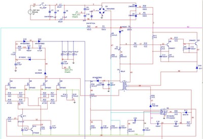
A Power Factor Correction (PFC) board has been obtained from an old Sun Microsystems Spark450 power supply (part number 300-1359-xx). This board contains all necessary components for a 650-watt inverter. However, the complete PFC circuit is not fully detailed...
This weblog discusses electronic circuit schematics, PCB design, DIY kits, and electronic project diagrams. The 1K resistors in the circuit are significant as they allow the LEDs to activate at different audio levels. While these resistors can be modified,...
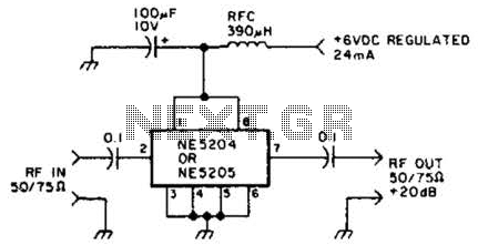
The Signetics NE5204 or NE5205 can be utilized in this audio frequency to 350-MHz (-30 dB) preamplifier. For a requirement of 600 MHz at 3 dB, the NE5205 should be employed. The noise figure is 4.8 dB at 75...
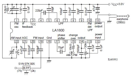
This portable AM/FM radio circuit is designed using the LA1800 integrated circuit (IC) along with several external components. The circuit diagram illustrates that the LA1800, manufactured by Sanyo Semiconductors, requires only a few additional components. The output signal is...