
I have a 315bl excavator. Engine intermittently shut off on

The electrical schematic for the 315BL excavator encompasses a variety of circuits designed to manage power distribution, engine starting, and auxiliary functions. The primary circuit begins at the battery, which provides the necessary voltage and current to the entire system. The disconnect switch allows for safe disconnection of the battery, preventing accidental short circuits during maintenance.
The power circuit includes multiple breakers to protect against overloads, ensuring that each component operates within its specified limits. The main relay acts as a control point for energizing various circuits, including those for starting the engine and powering auxiliary systems.
The engine start/stop circuit is crucial for operation, utilizing a combination of relays and switches to ensure that the engine can only be started under safe conditions. The neutral start switch prevents the engine from starting unless the transmission is in the neutral position, providing an additional layer of safety.
For cold weather operations, the starting aid circuit is designed to facilitate engine ignition by preheating the engine components, thereby reducing the risk of failure during low-temperature conditions.
The low current circuit activates various components such as lights and wipers, enhancing the operator's visibility and safety during operation. The switch panel serves as the user interface for controlling these components, allowing for easy access and operation.
Overall, the schematic integrates these elements into a cohesive system, ensuring reliable operation of the excavator while maintaining safety and performance standards. Each component's interaction is carefully designed to prevent faults and ensure the machine operates efficiently under varying conditions.A 315bl excavator. Engine intermittently shut off on its own, but will start back up without a problem. Now machine will not shut off when key is off, happens every day now. I sometimes have to choke off air intake to shut down. most of the time the engine will restart then shut off. (1) Disconnect switch. (2) Batteries. (3) Power circuit.(4) Breaker 1. (5) Main relay. (6) Fuse box. (7) Low current circuit. (9) Cigar lighter. (10) Starter control relay. (11) Starter switch. (12) Neutral start switch. (13) Cab heater. (14) Air conditioner. (15) Lights. (16) Windshield wiper. (17) Windshield washer. (18) Start/stop circuit. (19) Starter motor. (20) Starter relay. (21) Alternator. (22) Horn. (23) Controller. (24) Switch panel. (25) Shut down solenoid. (26) Heater control unit. (27) Glow plug. (28) Charging circuit. (29) Timer relay. (30) Neutral start relay. (31) Battery breaker. (32) Breaker 2. (33) Breaker 3. (34) Fan relay. (35) Shut down timer. (36) Heater relay. This circuit supplies power to electric components and includes battery (2), disconnect switch (1), battery breaker (31), breaker 1 (4), breaker 2 (32), breaker 3 (33) and main relay (5). This circuit starts/stops the engine and includes starter control relay (10), starter motor (19), starter relay (20), timer relay (29), starter switch (11), shut down solenoid (25), neutral start relay (30), neutral start switch (12) and shut down timer (35).
Some machines are equipped with starting aid for cold weather starting purposes. The start aid circuit consists of glow plug (27), heater control unit (26) and heater relay (36). This circuit distributes power to several low current components. By operating switch panel (24), this circuit puts on lights (15) installed at chassis, cab and boom. Also, this circuit controls continuous or intermittent operation of the windshield wiper (16). (2) Battery. (10) Starter control relay. (11) Starter switch. (12) Neutral start switch. (19) Starter motor. (20) Starter relay. (21) Alternator. (25) Shut down solenoid. (29) Timer relay. (30) Neutral start relay. (42) Starter solenoid. (43) Shut down timer. When starter switch (11) is placed in ON position (39) with the hydraulic activation control lever in LOCKED position, there is current flow through timer relay (29) and neutral start switch (12) to neutral start relay (30). The coil of neutral start relay (30) is energized to be ready for the start operation. When starter switch (11) is placed in START position (40), there is current flow through neutral start relay (30) to starter relay (20).
The starter relay contacts are closed and there is current flow to terminal S of starter solenoid (42) from starter relay. NOTE: If switch (11) is placed in the ON position with the hydraulic activation control lever in UNLOCKED position, no current flows to starter relay (20) and the engine will not start.
When current flows to terminals of starter solenoid (42), contacts are closed and strong current flows from (+) terminal of battery (2) to B terminal of starter solenoid (42), which rotates motor (19) to start the engine. Once the engine starts, alternator (21) begins to generate electricity. Current signal is sent from P terminal of starter control relay (10). Terminal S of starter control relay (10) opens to turn the coil of starter relay (20) OFF. Starter motor (19) stops its rotation, which prevents the motor from being damaged due to over rotation.
When the starter switch is placed in OFF position (41), shut timer timer (43) supplies power for a certain period. Shut down solenoid (25) starts to move and stops fuel supply to the engine for 6 seconds, which stops the engine.
After the 6 seconds is over, the governor actuator opens fuel rack to make restart possible. If starter switch (11) is placed in the ON position before the 6 seconds pass, the governor opens the fuel rack at that time. Check the linkage first, spray it 🔗 External reference
Related Circuits
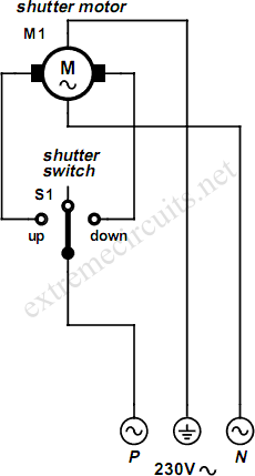
An electrically operated rolling shutter typically features a standard control panel equipped with a three-position switch that allows for up, down, and stop functions. The electrically operated rolling shutter system is designed to provide convenient control over the opening...
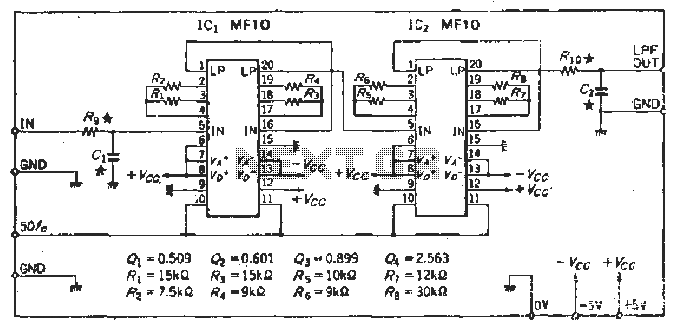
To create a Butterworth low-pass filter with a 12 dB/octave roll-off, four second-order (12 dB/oct) filter blocks are connected in series. This configuration is intended to achieve flat response characteristics across the frequency spectrum. The values for each stage...
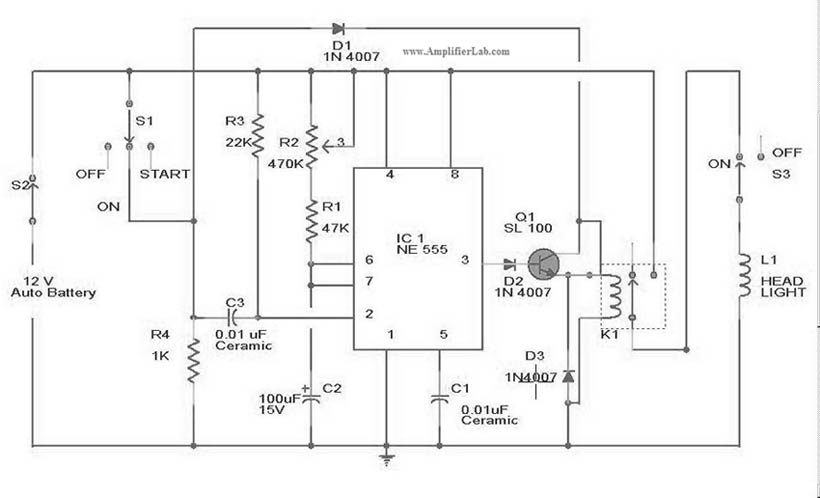
The circuit diagram for the automatic headlights turn-off circuit is presented here. This circuit can be installed in a car. The automatic headlights turn-off circuit is designed to enhance vehicle safety and convenience by ensuring that the headlights are automatically...
Most multimeters today have an auto turn-off feature built in. There is enough space in a multimeter enclosure, so why not install a simple circuit that... A multimeter's auto turn-off feature is designed to conserve battery life by shutting down...
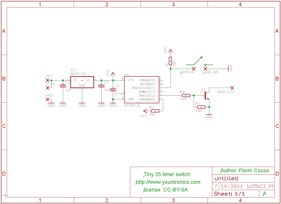
This project describes how to build a "soft touch" switch. By "soft touch" we mean that you have to push once to set device ON and push again to set device OFF. This kind of switch works by latching...

A simple yet effective circuit to generate a POTS-compatible ringing voltage can be constructed using National Semiconductor's LM4871 audio amplifier IC along with a dozen passive components. This circuit produces a sine-wave output of 1 W at approximately 70...