
IC-compatible crystal oscillator

The described circuit utilizes resistors R1 and R2 to maintain stable operating conditions for the NAND gates, which are crucial for reliable digital logic performance. These resistors help mitigate temperature-induced variations, ensuring consistent behavior across the specified temperature range. The selection of resistors should consider their thermal coefficients to maintain stability as environmental conditions change.
Capacitor C1 serves the critical function of decoupling DC components from the AC signals within the circuit. Its impedance must be carefully chosen to ensure it does not adversely affect the frequency response, particularly at the operating frequency. A low impedance value at the intended frequency will facilitate effective signal transmission while blocking any DC offset that may interfere with the logic levels of the NAND gates.
The crystal's operation in a series-resonant mode is essential for achieving the desired oscillation frequency. The use of AT-cut crystals is advantageous due to their inherent stability and low series resistance, making them ideal for applications in the 1 to 10 MHz frequency range. This low series resistance minimizes power loss and enhances the overall efficiency of the oscillator circuit.
The output waveform characteristics, including a nearly 50% duty cycle, indicate that the circuit is designed for balanced switching behavior, which is critical in digital applications to ensure proper timing and signal integrity. The chip-limited rise times suggest that the design may incorporate specific components to manage signal transitions, which can help reduce electromagnetic interference and improve overall performance.
Operating effectively from 0°C to 70°C indicates that the circuit is designed for typical commercial applications, where temperature variations are expected. Proper thermal management and component selection are essential to ensure reliable operation within this range, and careful consideration should be given to the thermal characteristics of all components involved in the circuit.Resistors Rl and R2 temperature-stabilize the NAND gates; they also ensure that the gates are in a linear region for starting. Capacitor CI is a dc block; it must have less than Vw ohm impedance at the operating frequency. The crystal runs in a series-resonant mode. Its series resistance must be low; AT-cut crystals for the 1- to 10-MHz range work well. The output waveshape has nearly a 50% duty cycle, with chip-limited rise times. The circuit starts well from 0° to 70°C.
Related Circuits
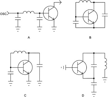
The open-loop concept of oscillator design is often met with considerable skepticism by engineers familiar with classic oscillator terminology. For clarity, consider Figure 2-4A, where the oscillator cascade is illustrated with only the RF components. The circuit is then...
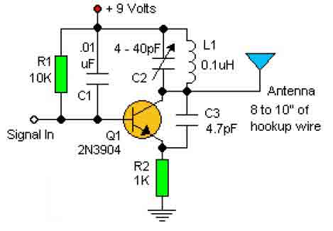
This basic RF oscillator circuit is easy to build and the components are not critical. Most of them can be found in your junk parts box. The L1 antenna coil can be made by close winding 8 to 10...
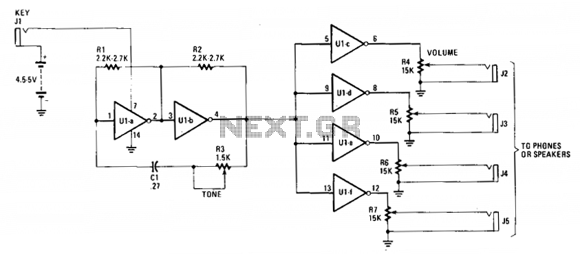
The cost-effective 7404 hex-inverter provides sufficient amplification to accommodate a broad spectrum of transducers. Engaging the switch completes the battery circuit, supplying four to five volts to the 7404. The bias for the first two inverter amplifiers (Ula and...
This circuit is a conventional Pierce type oscillator that utilizes a JFET. It employs fundamental mode crystals and demonstrates good performance and reliability when a low noise JFET is used. The feedback is regulated by the capacitance C1, which...
This circuit was designed to drive an impact counter, utilizing the ICL8038 as its core component. It is intended for a motor that operates a conveyor, with the motor featuring a feedback system known as a tachogenerator. Only a...
The 555 Timer IC operates in three modes: monostable, astable, and bistable/Schmitt trigger. This article will focus on its astable mode. The astable mode of the 555 Timer IC is characterized by its ability to generate a continuous square wave...