
Tilt Sensor Alarm Circuit

The tilt sensor alarm circuit utilizes a tilt sensor, which is a device that detects the orientation of an object. When the object tilts beyond a certain angle, the sensor triggers the alarm circuit. The primary components of this circuit include a tilt sensor, a transistor, a resistor, and a power supply.
The tilt sensor typically consists of a conductive ball within a sealed enclosure that connects two conductive contacts. When the sensor tilts, the ball rolls and completes the circuit, allowing current to flow. This current is directed to the base of the transistor, which acts as a switch.
When the transistor is activated, it allows current to flow from the collector to the emitter, which can be used to drive an alarm or indicator, such as a buzzer or LED. The resistor is used to limit the current flowing into the base of the transistor, ensuring it operates within safe parameters.
The power supply for the circuit can be a standard battery, ensuring portability and ease of use. The circuit can be assembled on a breadboard for prototyping or soldered onto a printed circuit board (PCB) for a more permanent solution.
This simple tilt sensor alarm circuit is ideal for applications such as security systems, where it can alert users to unauthorized movement or tampering of objects. Its low cost and ease of assembly make it accessible for hobbyists and professionals alike.Ultra simple circuit of the tilt sensor alarm presented here can be fabricated using readily available inexpensive components. The circuit is a true transi. 🔗 External reference
Related Circuits

Figure 1 illustrates an enhanced trigger timing circuit that utilizes two Programmable Unijunction Transistors (PUTs). When a set signal is applied, the circuit is activated, causing transistor VT1 to enter the conduction state and energizing relay K. This action...

The circuit consists of inverter and charger sections. The inverter section utilizes the NE555 timer, while the charger section is based on the LM317 adjustable regulator. In the inverter section, the NE555 is configured as an astable multivibrator, generating...
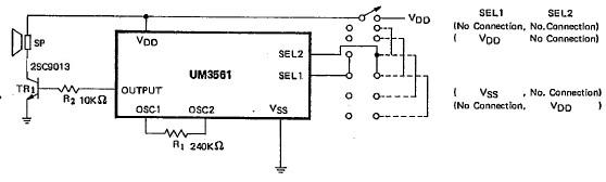
This siren alarm circuit diagram utilizes the specialized integrated circuit (IC) UM3561, which is a low-power CMOS large-scale integration (LSI) device specifically designed for such applications. The UM3561 incorporates all necessary components, including an oscillator, selector circuits, and programmed...
When the sensor detects movement in a room it will take a burst of 10 photos with the digital camera. Each photo is taken at 0.5sec interval. After the 10 photos, the camera waits 3 seconds for further movement...

The micro ampere meter presented here functions as a DC millivolt meter. It achieves full-scale deflection with a 0.1V input. The current to be measured flows through a known resistance R, and the voltage drop across this resistance is...

The first reverberator presented is based on the TDA1022, which is the most commonly used BBD (Bucket Brigade Device). Adjustments for proper functionality of the reverberator are required before connecting the power supply. The TDA1022 is a versatile BBD that...