
strobe light controller

The project involves several key components and circuits designed to work in tandem to achieve the desired aesthetic lighting effect. The voltage doubler circuit is critical for stepping up the voltage from 5V to a usable level for the 12V LED strips. This circuit typically employs a configuration of capacitors and diodes to achieve the voltage doubling effect. The choice of diodes and capacitors is essential, as they must be rated for the expected voltage and current levels.
The NE555 timer is a versatile component widely used in timing applications. In this astable multivibrator configuration, it generates a continuous square wave output, which is essential for creating the strobe effect for the LED strips. The output frequency can be adjusted using the potentiometer, allowing for customization of the strobe light's flashing rate. This flexibility enables the user to create various lighting effects, enhancing the aesthetic appeal of the setup.
The successful integration of these components results in a functional and visually appealing lighting system. The careful selection of components, along with the modifications made to accommodate local availability, demonstrates a practical approach to electronics design. The final device not only serves its intended purpose but also showcases the application of fundamental electronic principles in real-world scenarios.After having its engine and other mechanical parts restored to its optimum condition, the next thing I had in mind is to add aesthetic lighting. I went to a local electronics store and found these 12V DC Operated LED Strip. These are perfect for what I had in mind. Luckily, I remembered the voltage doubler circuit introduced to us in our Electroni cs class during my college years. The voltage doubler circuit introduced to us at that time needs an AC input. Though its not the right circuit for my problem but it gave me a reason to look for a voltage doubler circuit that works with DC input. The search led me to this very cool site full of interesting useful circuits, the. Out from which I got this circuit. This site did not only post the circuit schematics but also a detailed description of how the circuit works.
Since some of the components shown in the circuit schematics is not locally available, I had to replace them with similar components that are available here in my place. The schematics of the modified circuit is shown in figure below. I tested this circuit using a 5V DC input. The output voltage measured, using my analog multimeter, is 8V. Theoretically, it should have been 10V but due to the diode and transistor P-N junction threshold voltages, the output voltage is minimized to 8V.
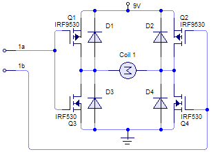
Tested this circuit again using the battery of my motorcycle and with the LED Strips connected to the output port. As can be observed, the LED Strip lights up brightly. The power supply part is done. The next part is the strobe controller which I will be calling as Alitaptap. Alitaptap is the Filipino term for firefly. I have decided to make one out of the NE555 Timer in Astable Multivibrator (with diode) Configuration.
The circuit schematics is shown below. This circuit is the same with the clock generator part of the voltage doubler circuit shown previously. Its only difference is that of its output frequency which is lower than that of the previous circuit.
I have included a potentiometer or variable resistor into it to allow for adjustments of the output Duty Cycle or simply put the ration between the on time and the total period. The complete device, which is composed of the voltage doubler from, the Alitaptapstrobe light controller and the LED strip, is shown in the following pictures.
🔗 External reference
Related Circuits
The first servo controller project at http://www.rentron.com/servo.htm had the com port fixed at com1. This new version will seek out the available com ports on your PC and then let you select the desired port and baud rates. It...
General Diagram of Motor Controller Manual PDF Download. The motor controller is an essential component in various applications, including robotics, electric vehicles, and industrial machinery. It regulates the operation of electric motors by controlling parameters such as speed, direction, and...
This project addresses the need for a simple circuit that can dim LED lights or control the speed of 12V DC motors. The circuit utilizes Pulse Width Modulation (PWM) to manage the effective or average current flowing through an...
Light Sensitive Switch is a simple project which operates a relay when the light falling on the LDR goes below a set point. More: Input - 12 V @ 55 mA Relay output - NC-C-NO Onboard preset to set the level Power-On...
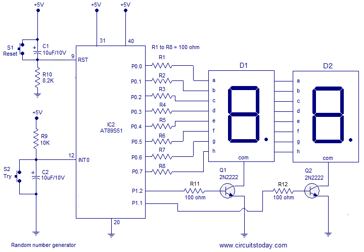
A simple random number generator utilizing the 8051 microcontroller. The AT89S51 is the controller employed in this setup. The circuit design for the random number generator based on the AT89S51 microcontroller involves several essential components and connections. The AT89S51 microcontroller,...
A good performance is achieved with a two-wire connection for a double touch switch that can function even if there is a break in the left part of the line. This switch is designed for general lighting control, such...